Toroidal type stepless transmission and stepless transmission

A transmission unit and infinitely variable speed technology, applied in the direction of transmission, friction transmission, belt/chain/gear, etc.

Inactive Publication Date: 2009-07-08
NSK LTD
View PDF5 Cites 25 Cited by
  • Summary
  • Abstract
  • Description
  • Claims
  • Application Information

AI Technical Summary

Problems solved by technology

As a result of this, even when the power rollers 11, 11 tend to move in the axial direction of the input shaft 1 due to elastic deformation or the like of the respective constituent parts based

Method used


Image

  • Toroidal type stepless transmission and stepless transmission
  • Toroidal type stepless transmission and stepless transmission
  • Toroidal type stepless transmission and stepless transmission

Examples


Embodiment Construction

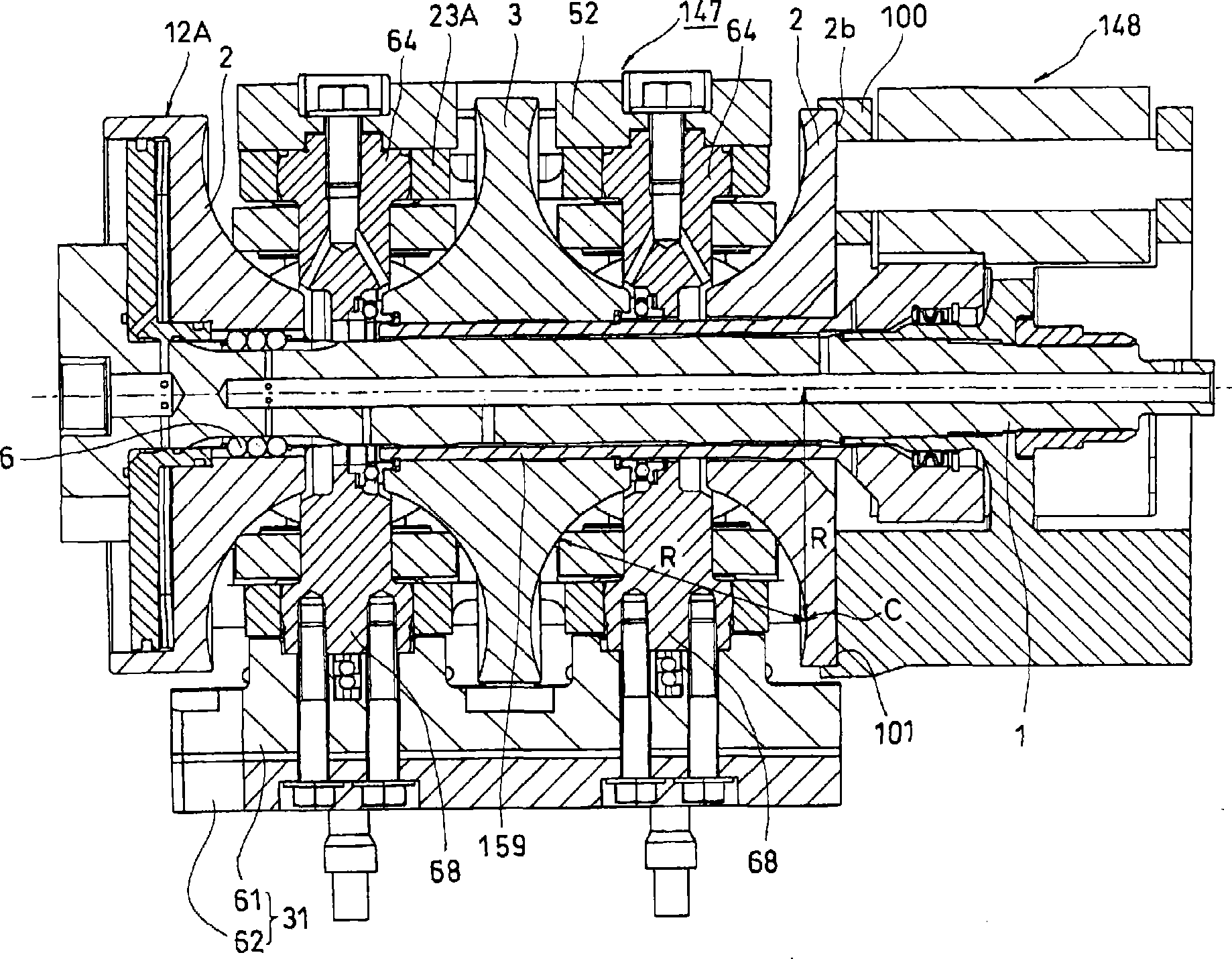
[0080] Hereinafter, embodiments of the present invention will be described with reference to the drawings. It should be noted that the present invention is characterized by the power transmission structure between the guide carrier of the planetary gear device and the disc of the annular continuously variable transmission unit, since it is otherwise structurally and functionally similar to the conventional structure already described above , Therefore, in the following description, only the characteristic parts of the present invention are described, and the other parts of the present invention are only given by giving Figure 9 to Figure 11 The same reference numerals are briefly described.

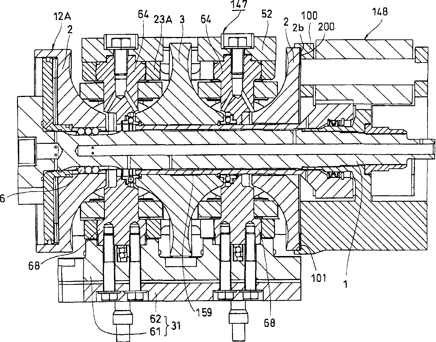
[0081] figure 1 A continuously variable transmission according to a first embodiment of the present invention is shown. As shown, in this embodiment, the input shaft 1 and the guide frame (power transmission member) 100 of the planetary gear unit 148 are integrated. The annular conti...


PUM


Abstract

A toroidal type stepless transmission where a carrier (100) and a disk (2) are in direct friction contact with each other to allow power transmission between the carrier (100) and the disk (2) by friction force. Accordingly, the transmission does not require processing of gears and claws on the disk or the carrier, which has been required conventionally. As a result, production processes are reduced to enable a considerable reduction in production costs.

Description

technical field [0001] The present invention relates to a toroidal continuously variable transmission unit that can be used as a transmission unit for automobiles or various industrial machines, and a toroidal continuously variable transmission unit including such a transmission unit. Background technique [0002] For example, a two-chamber toroidal continuously variable transmission unit used in automobiles is constructed as Figure 9 and Figure 10 shown. Such as Figure 9 As shown, the input shaft 1 is rotatably supported in the housing 50 , and two input discs 2 , 2 and two output discs 3 , 3 are connected to the outer circumference of the input shaft 1 . In addition, an output gear 4 is rotatably supported on the outer circumference of the middle portion of the input shaft 1 . The output discs 3, 3 are spline-connected to tubular flange portions 4a, 4a provided at the center portion of the output gear 4 (for example, refer to Patent Document 1). [0003] The input sh...

Claims


Application Information

Patent Timeline
IPC IPC(8): F16H15/38F16H37/02
CPCF16H2037/0886F16H37/086F16H15/38
Inventor 西井大树井上英司小林功久丰田俊郎
Owner NSK LTD
Why Eureka
Try Eureka