Tunnel kiln for firing ceramic items

A tunnel type, article technology, applied in the field of building material manufacturing, can solve the problems of bursting of roasted articles, and achieve the effect of increasing gas consumption, reducing heat consumption and reasonable temperature.

Inactive Publication Date: 2009-07-08
阿尔乔姆·茹里耶维奇·柴卡
View PDF0 Cites 3 Cited by
  • Summary
  • Abstract
  • Description
  • Claims
  • Application Information

AI Technical Summary

Problems solved by technology

Large temperature and humidity differences between hot

Method used


Image

  • Tunnel kiln for firing ceramic items

Examples


Embodiment Construction

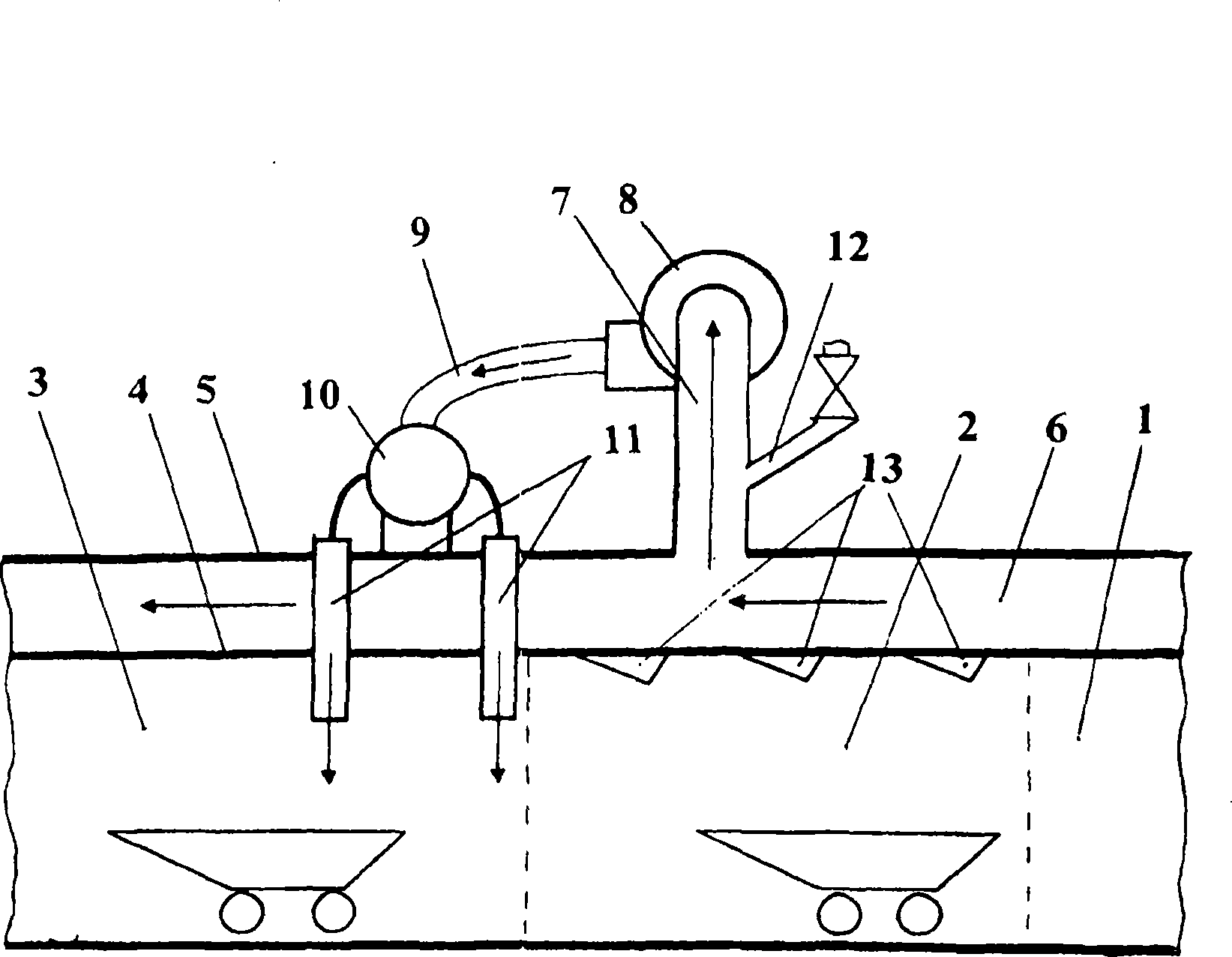
[0013] Position 1 represents the preheating section of the processing channel, position 2—firing section, and position 3—cooling section. Between the main vaulted roof 4 and the additional vaulted roof 5 there is an inner vaulted space 6 . The gas distribution (ventilation) system consists of a suction line 7, a ventilator 8, a feed line 9 and a collector-distributor 10 with a main pipe 11; Connected with the ventilator 8, the main pipe 11 of the collector-distributor 10 is directly output to the cooling section 3 near the firing section 2 of the processing channel. Position 13 indicates the burner located in firing section 2. The ventilation system may comprise several fans 8 with a corresponding number of connecting lines. However, the kiln can supply a certain portion of the gas supplied to the atmosphere and pipelines to feed hot gas to the preheating section 1 of the ceramic objects through exhaust ventilation (such constructional elements are not shown in the drawings ...


PUM


Abstract

The invention relates to engineering for firing natural materials and items made thereof and can be used for producing building ceramic units, in particular bricks. The inventive tunnel kiln for firing ceramic items comprises a working channel provided with ceramic item pre-heating, firing and cooling areas. Said working channel is defined by sidewalls, a main arch roof and an additional arch roof. The gas-distributing (ventilation) system of the tunnel kiln comprises at least one intake pipeline, a ventilator and a feeding pipeline, wherein the intake pipeline connects the inter-arch space of the kiln to the ventilator and the feeding pipeline connects the ventilator to the working channel cooling area and/or to a space between the firing area and said working channel cooling area. Said invention makes it possible to stabilise the quality characteristics of final products, to ensure more rational temperature operating conditions and to reduce the fuel consumption by using the inter-arch space heat. In addition, the supply of hot gas from said inter-arch space to the working channel makes it possible to compensate losses of heat taking place when the doors of the kiln are open.

Description

technical field [0001] The invention belongs to the technical field related to the roasting of natural materials and products thereof, and can be used in the manufacture of building materials (especially bricks). Background technique [0002] A known tunnel kiln comprises a channel and ventilation system divided into a product drying section, a firing section and a cooling section (patent RU 2187771, 2002). Hot gases come from the process channel and are fed to the process channel of the kiln in the drying section after being mixed with atmospheric air pumped in by a forced draft fan. These operations provide a reasonable way of kiln processing and item handling. However, in the roasting section, the top of the furnace is heated greatly. The heat is transferred to the outer roof space and thus cannot be utilized, i.e. unreasonable heat consumption occurs in the firing section. In addition, it is worth noting that local overheating of the roof can lead to deflection and des...

Claims


Application Information

Patent Timeline
IPC IPC(8): F27B9/00
CPCF27D17/008F27B9/02F27B9/3005F27B9/10
Inventor 阿尔乔姆·茹里耶维奇·柴卡
Owner 阿尔乔姆·茹里耶维奇·柴卡
Why Eureka
Try Eureka