Thermal energy distribution system and control method thereof

Pending Publication Date: 2021-11-04
E ON SVERIGE
View PDF7 Cites 1 Cited by
  • Summary
  • Abstract
  • Description
  • Claims
  • Application Information

AI Technical Summary

Benefits of technology

The patent describes a method for predicting demand peaks and efficiently utilizing heating or cooling facilities in a local distribution system. By using real-time data and control signals, the method can smooth out overall demand peaks, reducing the need for additional production plants. The method can also compensate for events such as weather, allowing for more efficient use of heat outtake. The reduced steering temperature determined by the local control unit can be used to control the distribution system's heat outtake, resulting in a more uniform outtake of heat for all distribution systems. The time resolved control signals sent periodically can provide efficient and reliable power steering, even in cases of broken contact. Overall, the method improves the efficiency of resource utilization and reduces the negative environmental impact of production plants.

Problems solved by technology

Events such as sporting events or parades may also cause occupants to leave their homes in large groups.
A problem occurs when a peak in demand must be handled, as fast-acting heating systems may typically be more expensive and less environmentally friendly to run than their slower counterparts.
Furthermore, it may be expensive to run said heaters at max capacity to compensate for the demand.

Method used


Image

  • Thermal energy distribution system and control method thereof
  • Thermal energy distribution system and control method thereof
  • Thermal energy distribution system and control method thereof

Examples


Embodiment Construction

[0042]The invention will by way of example be described in more detail with reference to the appended schematic drawings, which shows a presently preferred embodiment of the invention.

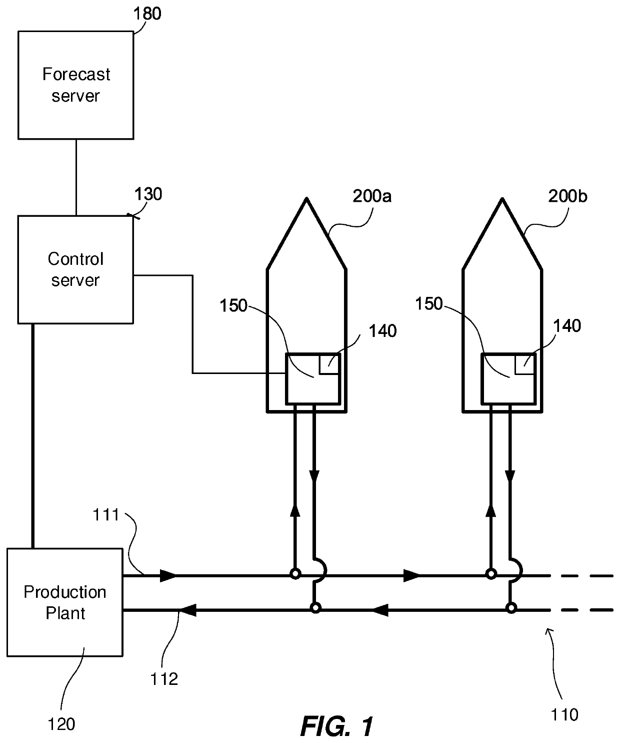
[0043]FIG. 1 shows a thermal energy distribution system, comprising a thermal energy distribution grid 110 and a production plant 120. The distribution grid 110 comprises a main line 111 providing heating or cooling medium from the production plant 120 and a return line 112 which transports heating or cooling medium to the production plant 120. The heating or cooling medium may be any fluid suitable for heating or cooling at a production plant 120 and transported by means of the main line 111 and return line 112, such as water. The heating or cooling medium will henceforth be referred to as “thermal fluid”. The production plant 120 may be a geothermal plant, an electrically powered plant for heating or cooling fluids, or may be driven by combustion of fuels, such as gas or oil. It is only important tha...


PUM


Abstract

The disclosure relates to a method for controlling a thermal energy distribution system, the method comprising:—determining forecast data pertaining to expected overall outtake of heat and / or cooling over time from a distribution grid by local distribution systems connected to the distribution grid, and to expected production capacity of heat and / or cooling in one or more production plants,—determining, at a control server, a time resolved control signal, the control signal being based on forecast data and being associated with at least one local control unit,—sending the control signal from the control server to the associated local control unit,—receiving the control signal at the associated local control unit,—regulating over time, in response to the control signal, the outtake of heat and / or cooling of the local distribution system from the distribution grid. The thermal energy distribution system is also claimed

Description

FIELD OF INVENTION[0001]The invention relates to a method for controlling a thermal energy distribution system. The invention also relates to a thermal energy distribution system.TECHNICAL BACKGROUND[0002]Within the field of comfort heating / cooling, it is a well-known phenomenon that demand for comfort heating or cooling may be heavily dependent on outer factors. For example, demand for comfort heating may be higher on a cold day, or on a day with weather phenomena such as blizzards or rainstorms. Demand for comfort heating may decrease during holidays, when occupants of residential buildings typically gather in larger groups, thus occupying fewer residences. Events such as sporting events or parades may also cause occupants to leave their homes in large groups. A problem occurs when a peak in demand must be handled, as fast-acting heating systems may typically be more expensive and less environmentally friendly to run than their slower counterparts. For instance, oil or gas heaters...

Claims


Application Information

Patent Timeline
IPC IPC(8): F24F11/65G05B13/02
CPCF24F11/65G05B13/026F24D10/00F24D2200/13G05D23/1934Y02B30/17Y02E20/14Y02B30/70Y02P80/10
Inventor ROSEN, PERSKOGSTROM, JACOBROSEN, FREDRIK
Owner E ON SVERIGE
Why Eureka
Try Eureka