Engine camshaft bearing cover

A bearing cap and camshaft technology, applied in the directions of engine components, machines/engines, mechanical equipment, etc., can solve the problems of poor layout, high cost, and large volume of the first bearing cap, and achieve compact oil circuit layout and reasonable structure. Effect

Active Publication Date: 2009-07-15
CHERY AUTOMOBILE CO LTD
View PDF0 Cites 12 Cited by
  • Summary
  • Abstract
  • Description
  • Claims
  • Application Information

AI Technical Summary

Problems solved by technology

However, the first bearing cap using this technology has the following disadvantages: when the engine adopts VVT (Variable Valve Timing) technology, the lubricating oil passage at the main journal of the camshaft and the VVT ​​oil passage are not easy to arrange. Therefore, the volume of the first bearing cap is larger than that of other bearing caps, and the structure of the oil circuit is complex, difficult to process and high in cost

Method used


Image

  • Engine camshaft bearing cover
  • Engine camshaft bearing cover
  • Engine camshaft bearing cover

Examples


Embodiment Construction
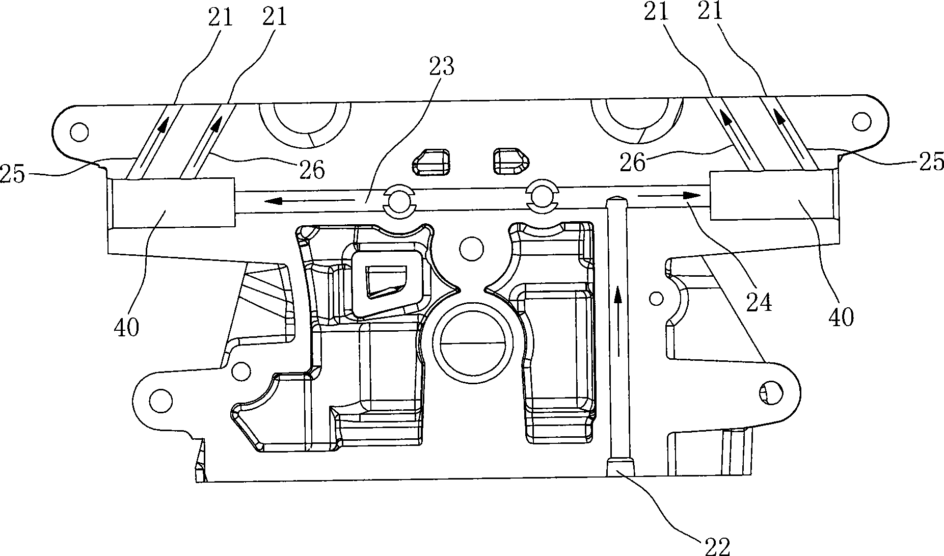
[0011] The VVT ​​oil circuit in the prior art can be referred to figure 2 When the engine is working, the oil supplied to the oil control valve 40 is first supplied by the oil pump to the main oil hole 22 at the cylinder head 20, and then the main oil hole 22 is divided into two parts connected to the oil control valve 40 In the oil passages 23 and 24, the oil is guided by the oil control valve 40 to selectively flow into the subsequent oil passages 25 (or 26) and 27 (or 28), and then continue to supply oil to the oil chamber of the phase controller.

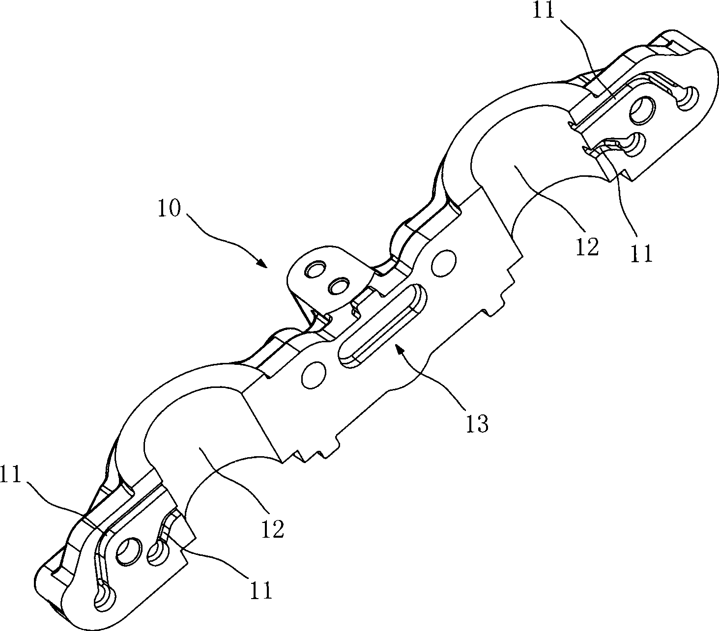
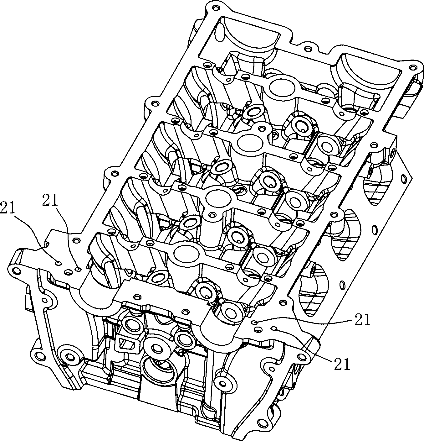
[0012] Such as figure 1 As shown, an engine camshaft bearing cap is provided with an oil groove 11 on the end surface where the bearing cap 10 is attached to the lower cylinder head 20. One end of the oil groove 11 communicates with the oil supply hole 21 on the cylinder head 20, and the other end Extending to the inner surface of the bearing hole 12 on the bearing cap 10, the oil flows through the oil control valve 40 and the oil...


PUM


Abstract

The invention belongs to the technical field of engines and particularly relates to a bearing cover of an engine camshaft. In the invention, an oil groove is arranged on the end face where the bearing cover is contacted with a cylinder cover below the bearing cover, one end of the oil groove is communicated with an oil supply hole on the cylinder cover, and the other end extends to the inner surface of a bearing hole on the bearing cover; the engine oil flows to the position of the oil supply hole on the cylinder cover through an engine oil control valve, and then flows into an oil chamber of a phase controller through the oil groove and oil channels on a camshaft in turn. The invention makes full use of the space of a first bearing cover of the camshaft and integrates the oil supply channel of VVT and the lubricating oil channel of the camshaft into a whole, furthermore, the whole oil channel is compact in distribution and reasonable in structure.

Description

Technical field [0001] The invention belongs to the technical field of engines, and in particular relates to an engine camshaft bearing cover. Background technique [0002] At present, most domestic engine camshafts are fixed on the cylinder head in a distributed manner, that is, an independent bearing cover is installed at each journal of the camshaft, and the bearing cover is assembled on the cylinder head with a positioning bolt, and then the cylinder The cover is processed to obtain the bearing hole. However, the first bearing cap using this technology has the following shortcomings: When the engine uses VVT (variable valve timing) technology, the lubricating oil circuit and VVT oil circuit at the main journal of the camshaft are not well arranged. Currently, machining is mostly used. Therefore, the volume of the first bearing cover is larger than that of other bearing covers, the oil circuit structure is complicated, it is not easy to process and the cost is higher. Summary...

Claims


Application Information

Patent Timeline
Patent Type & Authority Applications(China)
IPC IPC(8): F01M9/10F01L9/02F01L9/10
Inventor 曹健夏德刚
Owner CHERY AUTOMOBILE CO LTD
Why Eureka
Try Eureka