Automatic clutch and use thereof

A technology of automatic clutch and driving disc, which is applied in the field of mechanical transmission parts, can solve the problems of small transmission torque, fast wear, automatic separation of the driving disc and driven disc, etc., and achieve the effect of ensuring smooth operation

Active Publication Date: 2010-12-08
GUANGZHOU AUTOMOBILE GROUP CO LTD +1
View PDF1 Cites 0 Cited by
  • Summary
  • Abstract
  • Description
  • Claims
  • Application Information

AI Technical Summary

Problems solved by technology

The operating force of this clutch is small, but it still has the following disadvantages and deficiencies: the two ends of the transmission cable 3 are respectively connected to the ends of the rocking arms 2-1, 2-2, when the transmission cable 3 is connected to the driven disc 4 When the wrap angle is less than 180 degrees, because of the small contact surface between them, the torque transmitted from the driven disc 4 to the output shaft is also small; when the wrap angle of the transmission cable 3 to the driven disc is greater than 360 degrees, the transmission The two ends of the cable must overlap to form a cross. At this time, the width of the transmission cable needs to be reduced accordingly. The transmission cable with a smaller width not only has a small transmission torque and fast wear, but also breaks in severe cases.
Secondly, the structural layout of this clutch is in a non-centrosymmetric form, so that the clutch cannot achieve dynamic balance when it rotates, resulting in vibration, noise, clutch slipping, increased wear between parts, etc., and eventually the clutch cannot run smoothly.
In addition, this clutch uses a steel wire rope as a transmission cable. Under the action of its own weight, the steel wire rope will naturally sag, causing the engine to still contact the driven disk when the engine is idling, so that the driving disk and the driven disk cannot be completely and completely automatically separated.

Method used


Image

  • Automatic clutch and use thereof
  • Automatic clutch and use thereof
  • Automatic clutch and use thereof

Examples


Embodiment

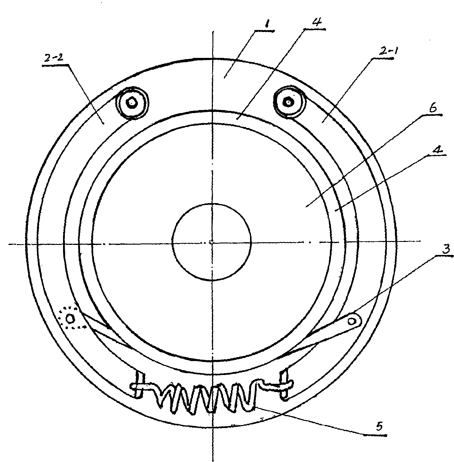
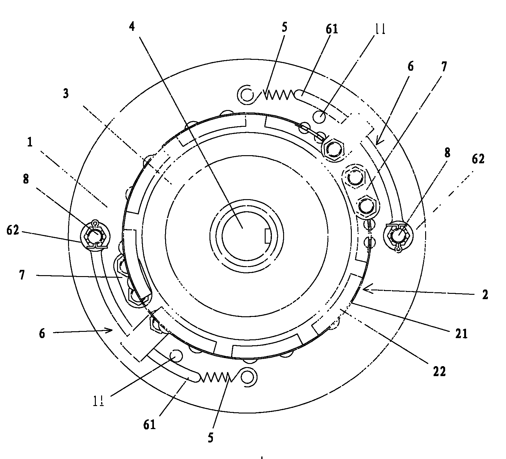
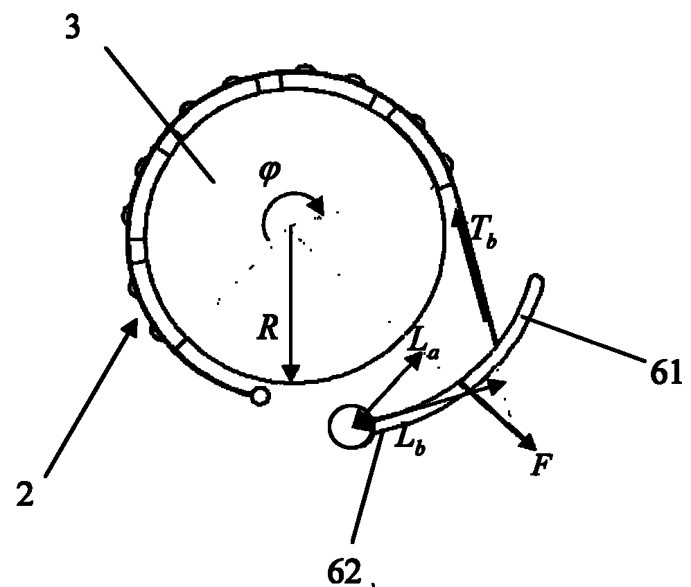
[0032] Such as Figure 2 ~ Figure 4 As shown, the automatic clutch of the present invention includes a driving disc 1, a driven disc 3, and a friction element 2. Two swing arms 6 are symmetrically arranged on the center of the driving disc 1, and each swing arm 6 is respectively provided with a fixed end 62 and a swinging arm 6. end 61, the fixed end 62 of each swing arm 6 is movably connected with the drive disc 1 in a rotatable manner through the rotating shaft 8 fixed on the drive disc 1, and the swing end 61 of each swing arm 6 can be connected by the spring 5 and other elastic parts are connected with the driving disc 1, one end of the friction element 2 can be fixedly connected with the driving disc through a fixed member such as a fixed shaft 7, and the other end of the friction element 2 surrounds the driven disc 3 for about 240 to 360 degrees (or 180~360 degrees) and then connected with the position close to the swing end 61 of the swing arm 6.

[0033] The above-men...


PUM


Abstract

The invention discloses an automatic clutch which comprises a driving disc, a driven disc, swing arms and a friction element. The driving disc is provided with at least two swing arms in central symmetry. Each swing arm is respectively provided with a fixed end and a swing end. Each fixed end is respectively connected with the driving disc directly. Each swing end is respectively connected with the driving disc by a spring. One end of the friction element is connected with the driving disc in a fixed way, and the other end is connected with the swing end of the swing arm or the position near the swing end by passing around the driven disc. The shrink moment of the spring is larger than or equal to the centrifugal moment of the swing end of the swing arm when the driving disc rotates at idle speed. The automatic clutch achieves the technical effect that the driving disc and the driven disc are separated thoroughly and are jointed mildly under the condition of ensuring the dynamic-static balance of the clutch. The automatic clutch works stably, has simple structure and low cost, has low vibration and noise at work, saves labor for operating, is convenient for maintaining and is favorable for popularizing and applying.

Description

technical field [0001] The invention relates to mechanical transmission components, in particular to an automatic clutch and its application. Background technique [0002] The clutch is located in the flywheel housing between the engine and the gearbox, and the clutch assembly is fixed on the rear plane of the flywheel with screws, and the output shaft of the clutch is the input shaft of the gearbox. During the driving process of the car, the driver can step on or release the clutch pedal as needed to temporarily separate and gradually engage the engine and the transmission, so as to cut off or transmit the power input from the engine to the transmission. [0003] Traditional clutches are mostly flat friction, and the friction force is determined by the spring pressure and the friction coefficient of the friction material. The operating force required to separate the clutch is also large, the structure is relatively complicated, and the operation and maintenance are inconven...

Claims


Application Information

Patent Timeline
Patent Type & Authority Patents(China)
IPC IPC(8): F16D43/18
Inventor 黄向东刘铁儿
Owner GUANGZHOU AUTOMOBILE GROUP CO LTD
Why Eureka
Try Eureka