Piston rod connecting device

A technology of connecting device and piston rod, applied in the direction of piston, cylindrical piston, fluid pressure actuating device, etc., can solve problems such as disadvantages and achieve the effect of avoiding the twisting of the piston

Active Publication Date: 2009-07-15
SCHAEFFLER TECH AG & CO KG
View PDF13 Cites 10 Cited by
  • Summary
  • Abstract
  • Description
  • Claims
  • Application Information

AI Technical Summary

Problems solved by technology

[0005] The disadvantage of the above solution is that the piston can be twisted in the housing with respect to the housing and the piston rod, since

Method used


Image

  • Piston rod connecting device
  • Piston rod connecting device
  • Piston rod connecting device

Examples


Embodiment Construction

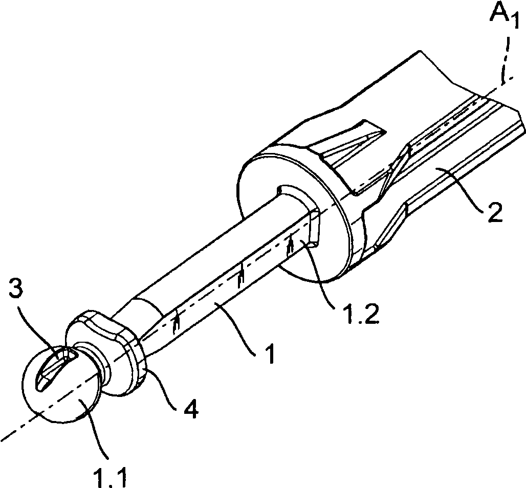
[0033] figure 1 A piston rod 1 with a spherical first end 1.1 is shown in . Connected to the second end 1.2 of the piston rod 1 is a push rod 2 which is connected to an actuating element not shown, for example a pedal. The spherical end 1 . 1 of the ball shaft 1 has two opposite groove-shaped recesses 3 , of which only one recess 3 is visible here due to the three-dimensional illustration. The recess 3 constitutes a first shaped element and is substantially aligned with the longitudinal axis A of the piston rod 1 1 Extend parallel and aligned. Attached at small intervals to the spherical first end 1 . 1 of the piston rod 1 is a flange 4 for fastening a sealing bellows (not shown).

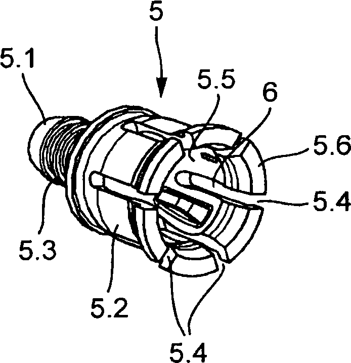
[0034] figure 2 A three-dimensional view of the adapter element 5 is shown in . The adapter element has a plug-in area 5.1 and a receiving area 5.2 for snap-in figure 1 The spherical first end 1.1 of the piston rod 1 is shown in . The plug-in area 5.1 is designed to be rotationally symmetri...


PUM


Abstract

The invenion relates to a piston rod connection device, which connects a piston rod with a piston, especifically for use in master cylinder of hydraulic actuation system in vehicl, wherein, the piston rod can be in pivoting movable coupling to a pistion which is axial movably mounted in housing along a longitudinal axis, such that the rod is pivotable around an angle in a pivoting plane. According to the invention, at least one first forming element is provided on a first end of the rod in fanction connection to the pistion, the first forming element corresponds to the second forming element thereby avoiding the piston torsion.

Description

technical field [0001] The invention relates to a piston rod connection and in particular for a master cylinder of a hydraulically actuated device in a vehicle, for example a master cylinder for actuating a hydraulic brake or clutch. Background technique [0002] Known from DE 195 23 215 B4 is a configuration of a piston for an active cylinder, wherein the piston consists of a piston skirt sleeve with a crown and two retaining shells arranged without play in the piston skirt sleeve, At the pedal-side end of the piston skirt sleeve, the retaining shell has a ball-and-socket-shaped recess in which the ball head of the piston rod engages and is held in a non-positive manner. The piston rod can perform a pivoting movement through its fastening by means of a ball head. [0003] DE 199 60 335 A1 describes a master cylinder in which the piston also includes two retaining shells which are seated in a piston skirt sleeve. The holding shell here also forms a spherical segment-shaped...

Claims


Application Information

Patent Timeline
IPC IPC(8): F16J1/14F16J1/22F16D65/20F16D25/08
CPCF15B15/1447F15B7/08F16J1/12F16J1/22F16D2025/081
Inventor Y·克里斯蒂安D·R·L·西费勒特
Owner SCHAEFFLER TECH AG & CO KG
Why Eureka
Try Eureka