Power transmission control device, power transmitting device, non-contact power transmitting system, and electronic instrument

A technology of power transmission device and control device, applied in circuit devices, electromagnetic wave systems, battery circuit devices, etc., can solve problems such as equipment damage, and achieve the effect of suppressing power consumption and high convenience of use

Active Publication Date: 2009-07-15
SAMSUNG ELECTRONICS CO LTD
View PDF1 Cites 14 Cited by
  • Summary
  • Abstract
  • Description
  • Claims
  • Application Information

AI Technical Summary

Problems solved by technology

For example, if power is wrongly transmitted to non-compliant power receiving side equipment, the equipment may be damaged
[0007] In addition, even in the case of power transmission to a standard-compliant power receiving side device, when the power transmissio

Method used


Image

  • Power transmission control device, power transmitting device, non-contact power transmitting system, and electronic instrument
  • Power transmission control device, power transmitting device, non-contact power transmitting system, and electronic instrument
  • Power transmission control device, power transmitting device, non-contact power transmitting system, and electronic instrument

Examples


Example

[0080] (First embodiment)

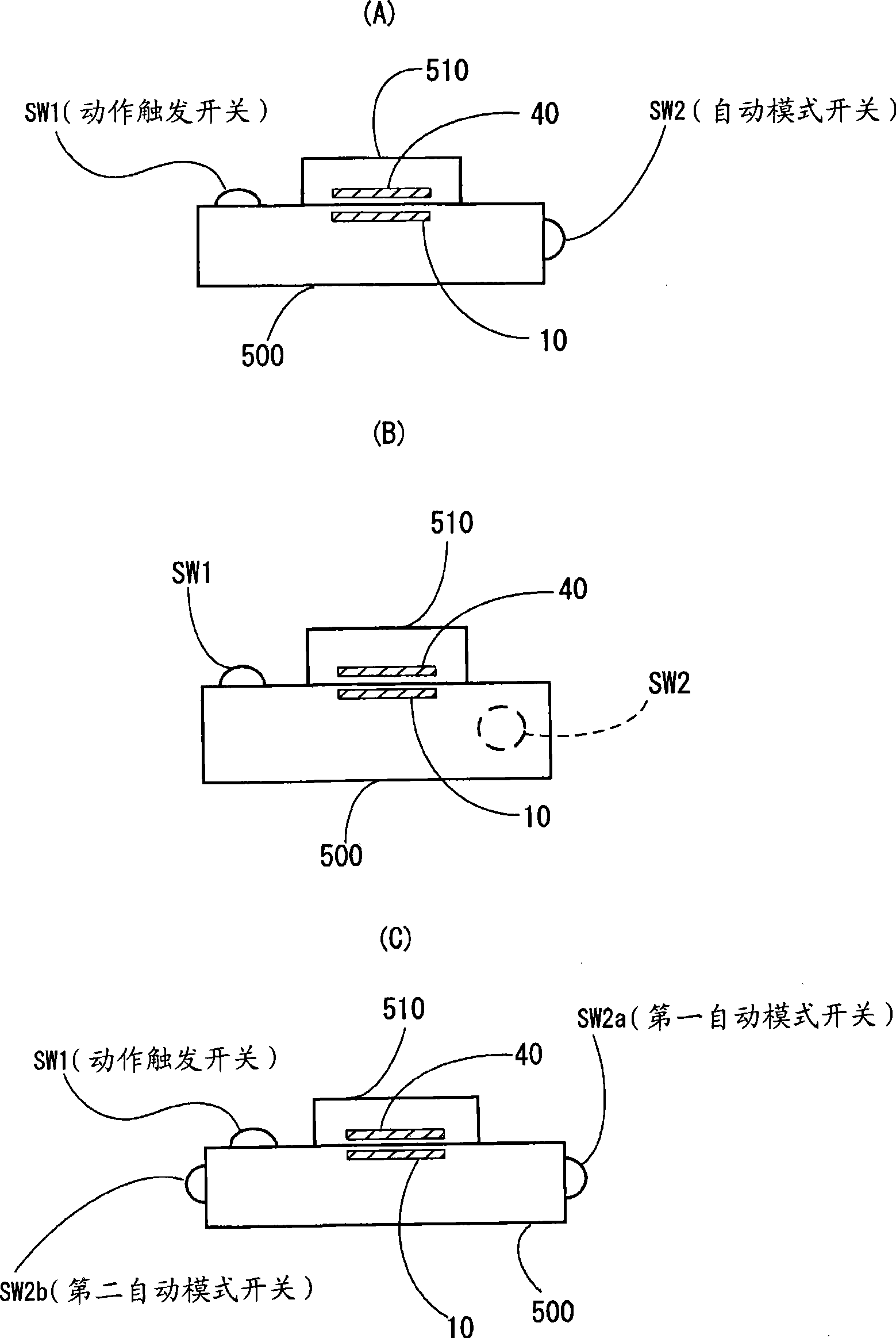
[0081] figure 1 (A)~figure 1 (C) shows an outline of a configuration example of a non-contact power transmission system that can switch between the switch mode and the automatic mode. figure 1 The non-contact power transmission system of (A) includes: a power transmission side device (for example, a charger (pallet)) 500; a power receiving side device (for example, a mobile phone terminal) 510, which is mounted on the power transmission side device 500 and passes through Contact power transmission charges the secondary battery (battery). The power transmission device 10 is built in the power transmission side equipment 500. In addition, the power receiving device 40 is built in the power receiving device 510. The power receiving device 40 can be mounted on the power receiving device 510 from the outside using an adapter or the like.

[0082] figure 1 (A) The non-contact power transmission system can switch between switch mode and automatic mode. A...

Example

[0151] (Second embodiment)

[0152] In this embodiment, the operation of the contactless power transmission system when the automatic mode is selected will be described.

[0153] (Outline of operation of power transmission device in automatic mode)

[0154] Figure 8 It is a schematic flowchart showing an example of the operation of the power transmission device in the automatic mode. As described above, the power transmission side control circuit 22 of the power transmission device 10 of the present invention can automatically detect the settings of the power receiving side equipment 510, and can also perform recharge management after a full charge. Therefore, the operation mode in which the power transmission device 10 automatically performs a series of operations is referred to as an automatic mode.

[0155] in Figure 8 As shown in the part enclosed by the thick dashed line, the operation of the power transmission device 10 in the automatic mode is roughly divided into "setti...

Example

[0297] (Third embodiment)

[0298] In this embodiment, the operation procedure of the non-contact power transmission system in the switching mode will be described.

[0299] (Outline of operation of power transmission device in switch mode)

[0300] Figure 24 It is a schematic flowchart showing an example of the operation of the power transmission device in the switch mode. As shown in the part enclosed by the thick broken line, the operation of the power transmission device 10 is roughly divided into "confirmation of the power transmission object (step SA)" before power transmission and "confirmation of the power transmission environment during power transmission (including before power transmission) (step SB)" .

[0301] As described above, the power transmission device 10 starts temporary power transmission when the switch (SW1) is turned on (steps S1, S2).

[0302] Next, it is confirmed whether the installation position of the power receiving device 510 is appropriate (step ...


PUM


Abstract

The present invention provide a power transmission control device, a power transmitting device, a non-contact power transmission system and an electronic instrument, desired to improve convenience to the user. A power transmission control device used for a non-contact power transmission system includes an operation mode switching terminal (AUTO) that receives an operation mode switch control signal that switches a mode between an automatic mode and a switch mode, a power transmitting device (10) starting normal power transmission in the automatic mode after installation of a power-receiving-side instrument (510) that includes a power receiving device (40) in an area in which power transmitted via non-contact power transmission can be received has been automatically detected, the normal power transmission supplying power to a load of the power-receiving-side instrument, and the power transmitting device starting the normal power transmission in the switch mode after an operation trigger switch (SW1) has been turned ON, an operation trigger terminal (SWONX) that receives an operation trigger signal that occurs due to an operation of the operation trigger switch (SW1), and a power-transmitting-side control circuit (20) that controls power transmission to the power receiving device (40) and changes an operation mode of the power transmitting device based on the operation mode switch control signal.

Description

technical field [0001] The invention relates to a power transmission control device, a power transmission device, a non-contact power transmission system, electronic equipment and the like. Background technique [0002] In recent years, attention has been paid to contactless power transmission (non-contact power transmission) technology that utilizes electromagnetic induction and enables power transmission even without contacts of metal parts. As an application example of this non-contact power transmission, charging of a mobile phone terminal or a household device (for example, a handset of a phone terminal or a watch) has been proposed. [0003] A non-contact power transmission device using a primary coil and a secondary coil is described in Patent Document 1, for example. [0004] Japanese Patent Laid-Open No. 2006-60909 [0005] In a non-contact power transmission device, for example, in order to achieve a longer life of a battery (storage battery) of an electronic dev...

Claims


Application Information

Patent Timeline
IPC IPC(8): H02J17/00H02J13/00H02J7/00
CPCY02E60/12Y04S40/126Y04S40/127Y02E60/7861Y02E60/7853Y02E60/10
Inventor 大西幸太神山正之盐崎伸敬上条贵宏长谷川稔曾我部治彦
Owner SAMSUNG ELECTRONICS CO LTD
Why Eureka
Try Eureka