
Speed regulating electricity generator with constant frequency

A technology of speed regulation and main shaft, which is applied in the direction of controlling generators, electric components, electrical components, etc., can solve the problems of high cost, complex inverter structure, high failure rate, etc., and achieve low energy consumption, simple structure, and low maintenance costs low effect

Inactive Publication Date: 2009-07-15
王光顺
View PDF0 Cites 6 Cited by
  • Summary
  • Abstract
  • Description
  • Claims
  • Application Information

AI Technical Summary

Problems solved by technology

[0002] In order to meet the requirements of grid-connected power generation, high-power low-speed multi-pole generators such as wind turbines and hydroelectric generators need to output voltages of the same frequency at different speeds. Most direct drive generators now use rectification-inversion-frequency conversion Electronically adjust the output frequency by electronic means. Due to the complex structure, high failure rate and high cost of the inverter, it has become a major obstacle for wind power and hydropower generators to be connected to the grid for power generation.

Method used


Image

  • Speed regulating electricity generator with constant frequency
  • Speed regulating electricity generator with constant frequency
  • Speed regulating electricity generator with constant frequency

Examples


Embodiment Construction

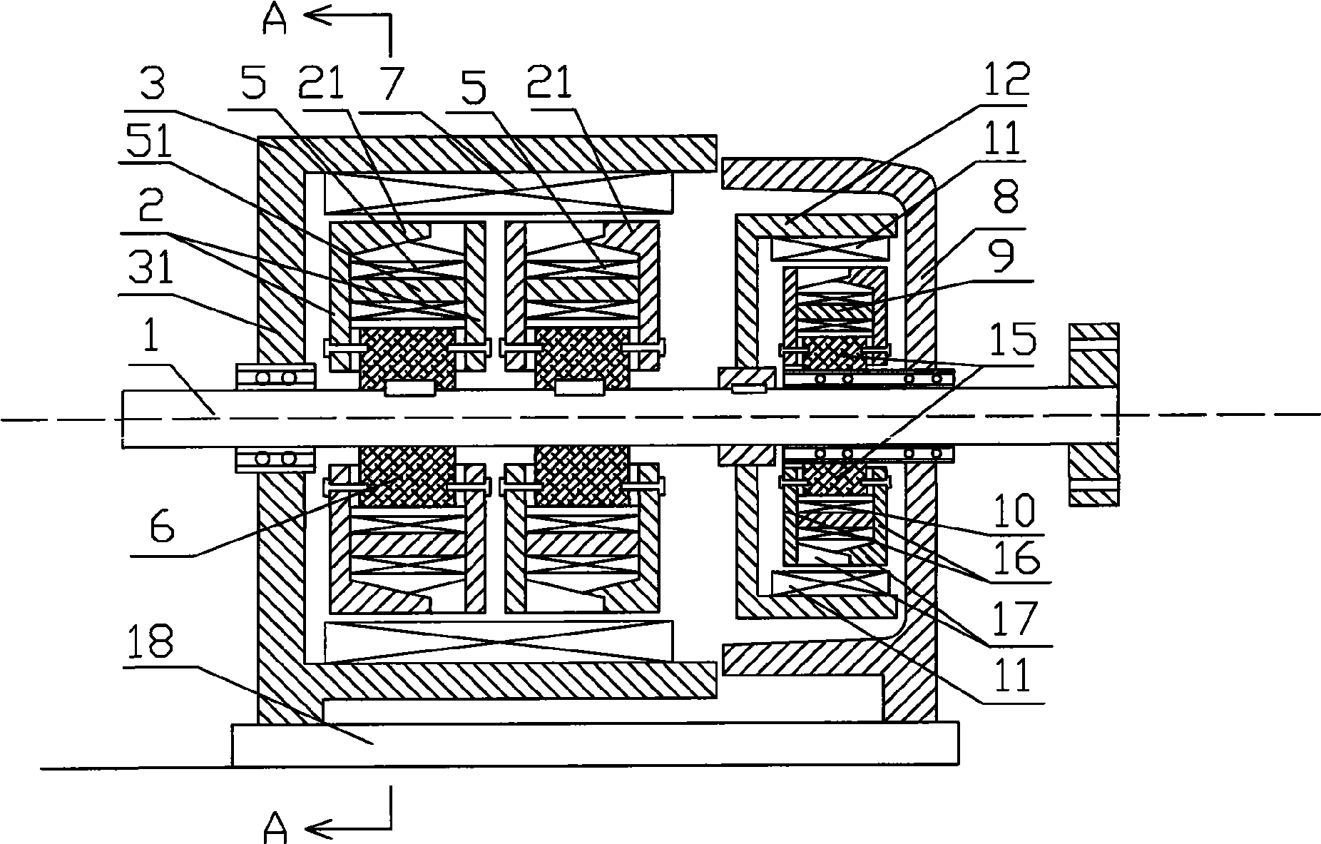
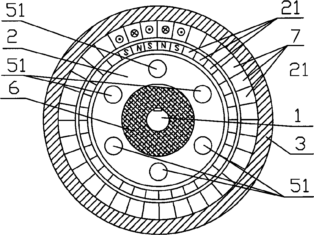
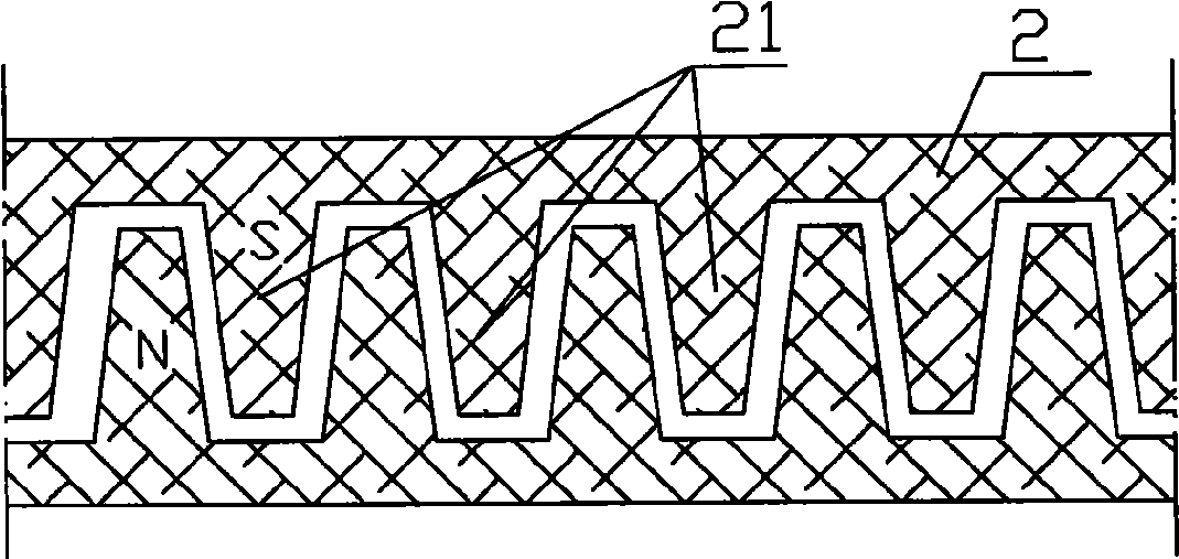
[0020] Such as figure 1 As shown, the speed-adjusting constant-frequency generator of the present invention includes a main shaft 1, a rotor fixedly installed on the main shaft 1, and a stator 3 surrounding the rotor, and the stator 3 is installed on the main shaft 1 through bearings. The rotor includes a claw pole plate 2, an iron core 51, and a rotor coil 5. The iron core 51 is fixedly installed between two opposing claw pole plates 2. The claw pole plate 2 is disc-shaped and made of a material with good magnetic permeability. Even pairs of tooth-shaped claw poles 21 are evenly distributed along the periphery of the peripheral portion thereof. The shape of the claw poles 21 is approximately trapezoidal. Such as figure 2 , image 3 As shown, two claw pole plates 2 are arranged relatively parallel in the form of staggered claw poles 21 . The claw pole plate 2 is fixedly installed on the main shaft 1 through the installation hole in its center, and a plurality of iron cores...


PUM


Abstract

The present invention relates to a speed governing frequency constant electricity generator that suitable for low speed multi-polar generator, which comprises a chief axis, a rotor fixedly mounted on the chief axis and a stator surrounds the rotor, wherein the stator is mounted on the chief axis through bearings; the rotor comprises claw pole plate, iron core and rotor coil, wherein the iron core is fixedly mounted between two claw pole plates that against each other; the claw pole plates are fixedly mounted on the chief axis through mounting holes in center; a plurality of iron cores are distributed around the chief axis evenly with rotor coil winding on them; the stator is in drum shape with one end of the drum wall fixedly connecting a shell cover; center of the shell cover is pluged on the chief axis through bearings; stator coil fixedly mounted on the inner side of the drum wall matches with the rotor coil; a terminal cap is mounted through bearings on the chief axis on the other side of the drum wall; the inside of the terminal cap is fixedly connected with a auxiliary stator, wherein the auxiliary stator comprises a auxiliary iron core and a auxiliary stator coil winding on the auxiliary iron core.

Description

technical field [0001] The invention relates to a generator, in particular to a speed-regulating constant-frequency generator suitable for low-speed multi-pole generators. Background technique [0002] In order to meet the requirements of grid-connected power generation, high-power low-speed multi-pole generators such as wind turbines and hydroelectric generators need to output voltages of the same frequency at different speeds. Most direct drive generators now use rectification-inversion-frequency conversion Electronically adjust the output frequency by electronic means. Due to the complex structure, high failure rate and high cost of the inverter, it has become a major obstacle for wind and hydro generators to be connected to the grid for power generation. Contents of the invention [0003] The purpose of the present invention is to provide a speed-regulating constant-frequency generator with simple structure, low speed, direct connection to the grid, and changing the sp...

Claims


Application Information

Patent Timeline
Patent Type & Authority Applications(China)
IPC IPC(8): H02K16/02H02K1/22H02K1/12H02K7/08H02K7/14H02P9/48
Inventor 王雪霖王光顺
Owner 王光顺
Learn More