Hydraulic energy recovery system

A technology of energy recovery and hydraulic circuit, applied in the field of hydraulic circuit, can solve problems such as limitation, affecting the overall performance of the circuit, and impossible adjustment

Inactive Publication Date: 2009-07-15
POCLAIN HYDRAULICS IND
View PDF0 Cites 11 Cited by
  • Summary
  • Abstract
  • Description
  • Claims
  • Application Information

AI Technical Summary

Problems solved by technology

[0008] Therefore, the possibility to store liquid during the energy recovery phase and to transfer the drive boost during the energy transfer phase is relatively limited, which undoubtedly has a negative impact on the efficiency of the circuit and thus its overall performance
In other words, the reduction in fuel consumption is not optimized
[0009] Of course, when a low-pressure accumulator is used as a low-pressure liquid source, since the low pressure is determined by the low-pressure accumulator at this time, it is impossible to adjust, so the above-mentioned difficulties will also be encountered

Method used


Image

  • Hydraulic energy recovery system
  • Hydraulic energy recovery system
  • Hydraulic energy recovery system

Examples


Embodiment Construction

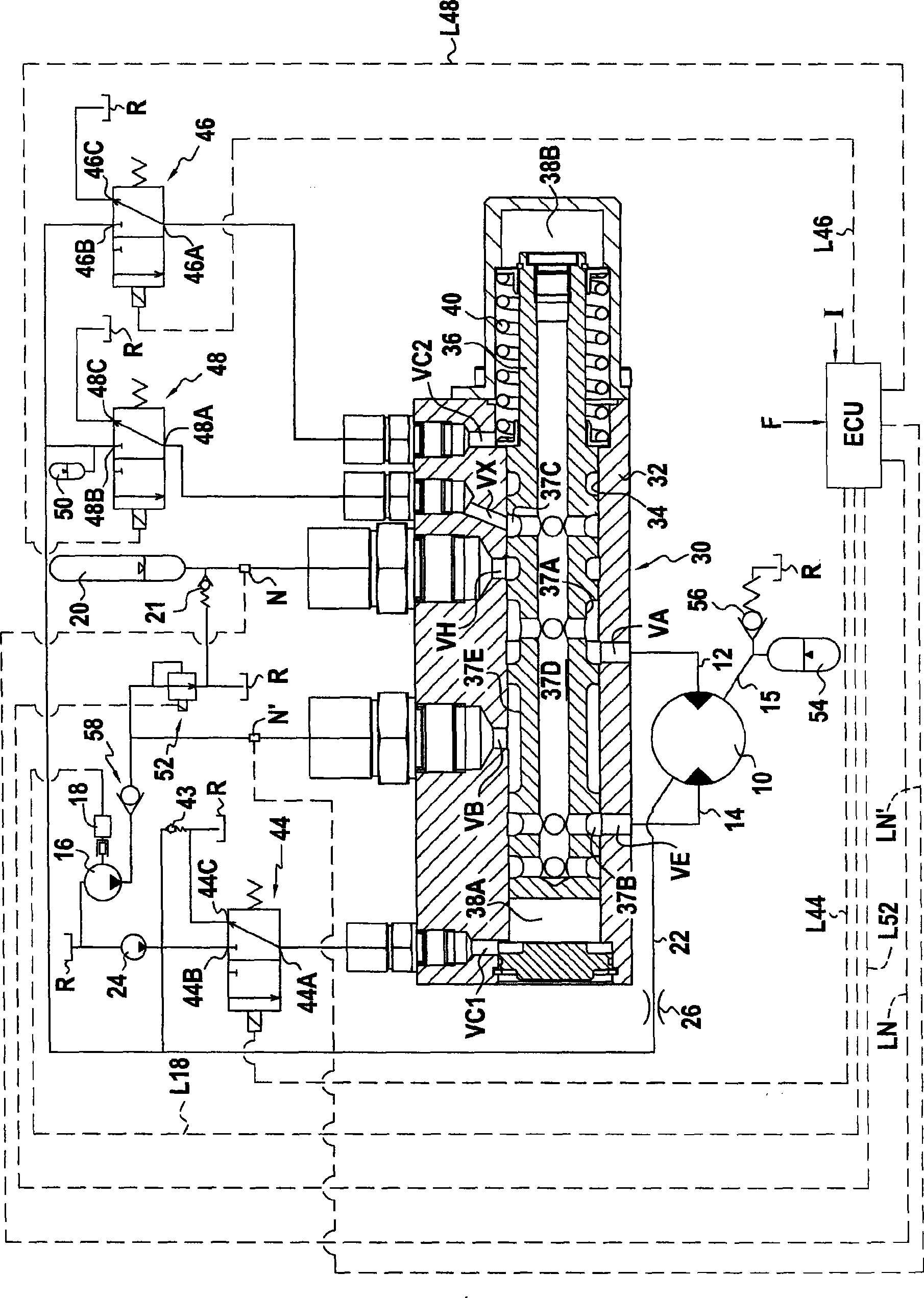
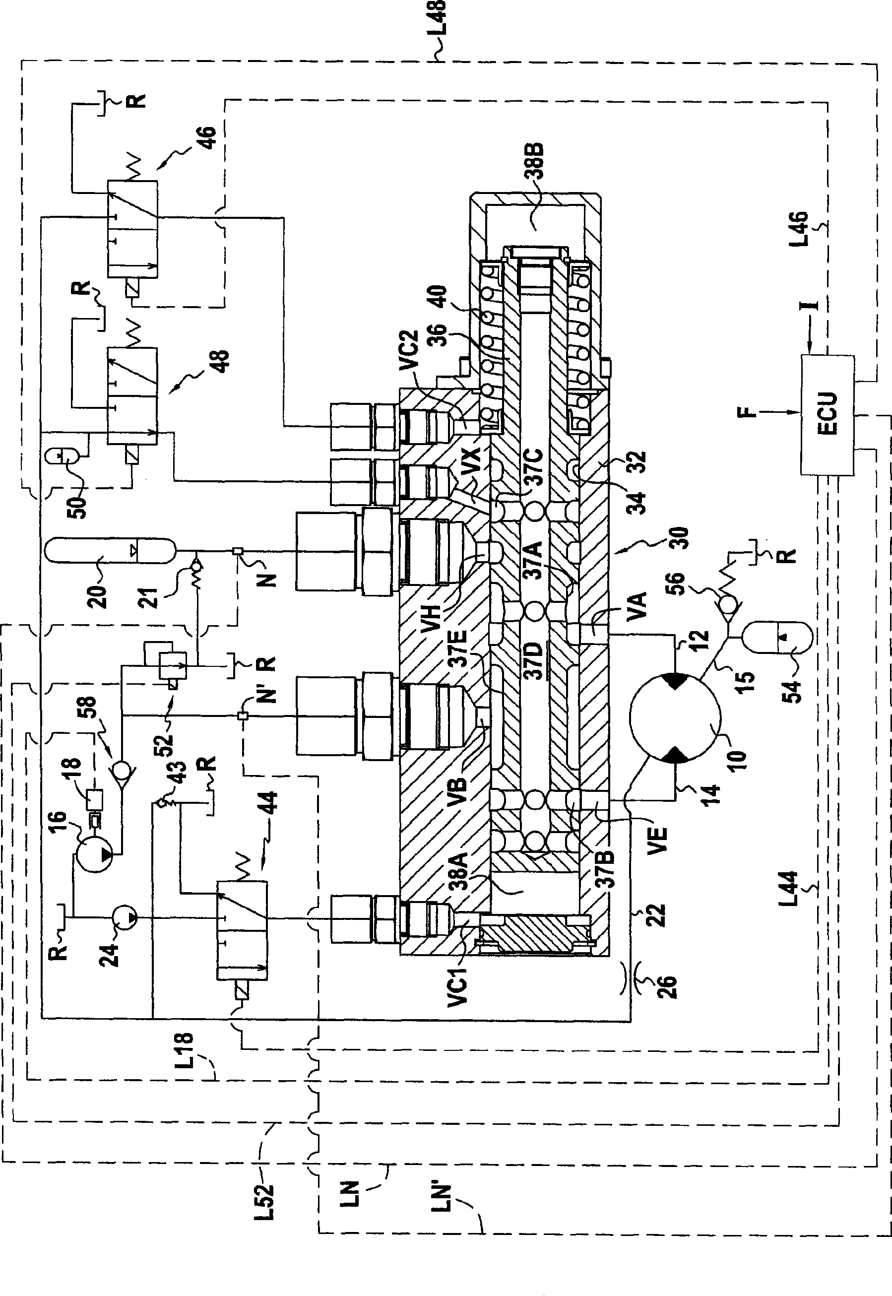
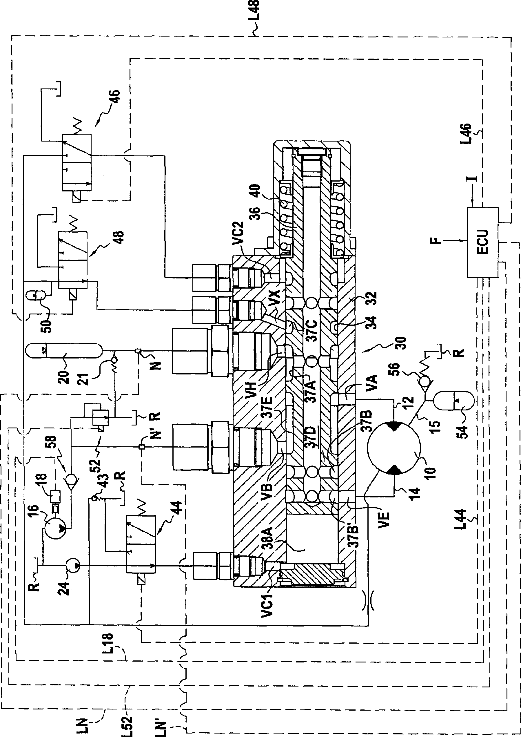
[0032] exist Figure 1A to Figure 1E The circuit shown in includes a hydraulic motor 10 having two main conduits 12 and 14 for supplying fluid to or draining fluid from said motor. The circuit also includes a low pressure liquid source 16 formed by a high flow rate booster pump pumping liquid from a pressureless reservoir R (reservoir at atmospheric pressure). The pump is selected to be adapted to deliver fluid at a velocity sufficient to feed fluid into the hydraulic motor when the motor is at its highest speed in an energy recovery configuration. When having multiple motors in a circuit, it is preferable to use the same high flow rate booster pump sized, when the motor is at its highest speed, to supply fluid to the different motors sufficiently without creating The velocity of the air pockets to transport the liquid.

[0033] The pump 16 is driven by an engine, which may be the vehicle's conventional propulsion engine. This circuit is provided with means for activating o...


PUM


Abstract

The invention relates to a hydraulic energy recovery system. The system includes at least one hydraulic motor (10), two main channels (12, 14) serving as the feed channel or the exhaust channel of said at least one motor, a low-pressure fluid source (16, 52, R) and a high-pressure accumulator (20) forming a high-pressure fluid source. Said system can operate in an energy recovery mode, in which the main feed channel (12) is connected to the low-pressure fluid source (16, 52) and the main exhaust channel (14) is connected to the high-pressure accumulator (20), and an energy release mode, in which the connections are reversed. The low-pressure fluid source comprises a high-flow booster pump (16) which can deliver a sufficient fluid flow in order to supply the at least one hydraulic motor (10) with fluid while said motor is operating at maximum speed in the energy recovery mode and an adjustable pressure limiter (52) which can be controlled in order to vary the pressure of the fluid at the outlet of the low-pressure fluid source.

Description

technical field [0001] The invention relates to a hydraulic circuit for recovering energy, the circuit comprising: at least one hydraulic motor; two main pipes for supplying liquid to or from said at least one hydraulic motor discharge; low pressure liquid source; and high pressure accumulator (accumulator), which forms a high pressure liquid source; the circuit is suitable for operation in energy recovery mode and energy transfer mode; in energy recovery mode, the supply main is connected to the low pressure liquid source , and the discharge main pipe is connected to the high-pressure accumulator; in the energy transfer mode, the supply main pipe is connected to the high-pressure accumulator, and the discharge main pipe is connected to the low-pressure liquid source. Background technique [0002] It is known that such circuits can be installed on vehicles to limit energy consumption. Such vehicles are "hybrid" vehicles, each of which has a conventional propulsion engine (s...

Claims


Application Information

Patent Timeline
Patent Type & Authority Applications(China)
IPC IPC(8): F16H61/40B60K6/12B60W30/18F16H61/4008F16H61/4043F16H61/4096F16H61/4139F16H61/4157
CPCF16H61/4008B60K6/12F16H61/4148F16H61/4157Y02T10/76Y02T10/6208F16H61/4139F16H61/4043F16H61/4096Y02T10/62
Inventor 让·赫伦吉勒·勒迈尔
Owner POCLAIN HYDRAULICS IND
Why Eureka
Try Eureka