
bundler

The technology of a binding device and a binding belt, which is applied in the field of binding devices for binding goods, can solve the problems of insufficient binding, increasing the difficulty of control, and small tension force of the binding belt, etc., and achieves reasonable line layout, easy implementation, and overall structure simple effect

Active Publication Date: 2012-02-22
ZHEJIANG TOPSUN LOGISTIC CONTROL CO LTD
View PDF1 Cites 2 Cited by
  • Summary
  • Abstract
  • Description
  • Claims
  • Application Information

AI Technical Summary

Problems solved by technology

[0005] However, it is impossible to know the tension of the binding belt during the use of the binding device, and it is difficult to control when using it, which often leads to damage to the goods caused by the binding being too tight, the binding belt breaks, or the transportation of the goods is affected because the binding is not tight enough
In addition, when binding goods, different goods or the same goods will have different strengths when binding in different positions, which further increases the difficulty of control
On the other hand, during transportation, due to bumps, vibrations, etc., the tension of the binding belt of the binding device may change. In some places, the tension of the binding belt is too large, and in some places, the tension of the binding belt is too high. Small
At this time, it is necessary to adjust the tension force, but the existing binding device cannot know the tension force of the binding belt, so it is very troublesome to adjust

Method used


Image

  • bundler
  • bundler
  • bundler

Examples


Embodiment 1

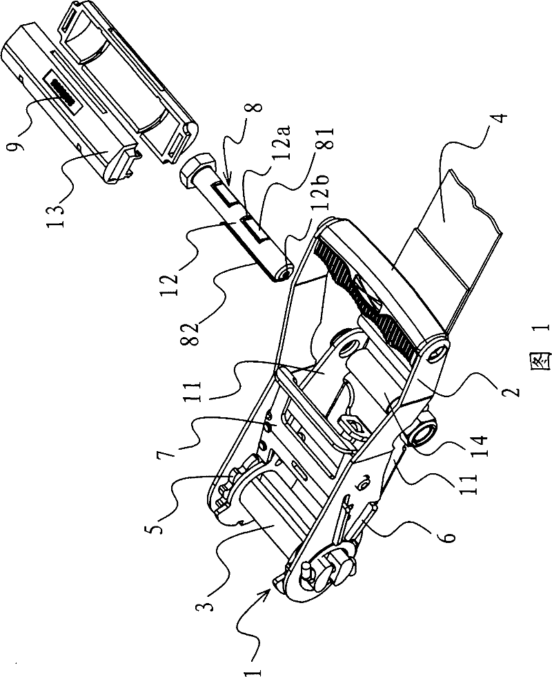
[0031] like figure 1 As shown, the binding device bracket 1, handle 2, reel 3, binding belt 4, movable belt hook, positioning belt hook, ratchet 5, tooth blocking plate 6, handle 7, sensor 8, display device 9 and other components.

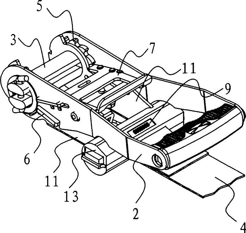
[0032] like figure 1 , 3 , 4 and 5, the bracket 1 includes two parallel side pieces 11 and a horizontal shaft 12, the handle 2 is hinged on the bracket 1 through a reel 3, and a ratchet 5 is fixed on the reel 3. The reel 3 passes through one end of the side body 11 , and the horizontal shaft 12 is fixed at the other end of the side body 11 . A binding strap 4 having a positioning strap hook fixedly connected to its outer end is coupled to the transverse shaft 12 of the bracket 1 . On the reel 3, another binding band 4 is wound on the outer end of which is fixed with a movable band hook. The bracket 1 is movably connected with a tooth blocking plate 6 whose end can be embedded between the ratchet teeth of the ratchet 5 , and the handle 2 is mova...

Embodiment 2

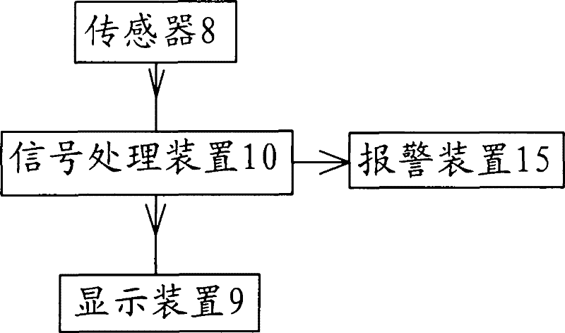
[0038] like Figure 7 As shown, in this embodiment, the sensor 8 is arranged on the above-mentioned binding band 4 , and the sensor 8 is connected with a wire 82 connected with the signal processing circuit 10 . When the binding device is in operation, the binding belt 4 is subjected to a tensioning force, and the sensor 8 provided on the binding belt 4 can easily detect the magnitude of the tensioning force, so as to grasp the working state of the binding device in time. The rest are similar to those in Example 1, and will not be repeated.


PUM


Abstract

The invention provides a binding device, which belongs to the technical field of machinery. It solves the problems that the existing binding device cannot detect the tension force of the binding belt in real time, the circuit layout is not reasonable enough, the overall structure is complicated, and the like. The binding device includes a bracket, a handle and a reel, the handle is hinged on the bracket through the reel, a binding belt is connected to the bracket, another binding belt is rolled on the reel, a ratchet is fixed on the reel, and other The end part can be embedded in the gear plate between the ratchet and the ratchet, and the handle is movably connected with a handle. The force-bearing part of the binder is also equipped with a sensor, which is connected with the signal processing circuit and can generate and The signal corresponding to the tension force of the binding belt is connected to the display device fixed on the binding device on the signal processing circuit. The present invention has the advantages of simple overall structure, reasonable line arrangement, easy implementation, and the sensor can detect the tension force of the binding belt in real time.

Description

technical field [0001] The invention relates to the technical field of binding tools, in particular to a binding device used for binding goods in the process of logistics and transportation. Background technique [0002] In the process of carrying goods by car, the goods usually need to be secured for safe and reliable delivery. Using ordinary nylon ropes or steel wire ropes for bundling is not only inefficient, but also laborious to operate; at the same time, it is also difficult to tie the goods tightly. The bundler can quickly and easily bundle and position the goods, so it is widely used and welcomed by the majority of logistics workers. [0003] At present, the binding device used in logistics and transportation is assembled from parts such as body, handle, ratchet, reel, handle, baffle, webbing, belt hook, spring and so on. The whole bundler has two strap hooks, namely the positioning strap hook and the movable strap hook. The positioning belt hook is fixedly connec...

Claims


Application Information

Patent Timeline
Patent Type & Authority Patents(China)
IPC IPC(8): B60P7/06B21F9/00B65B13/22
Inventor 阮卜琴
Owner ZHEJIANG TOPSUN LOGISTIC CONTROL CO LTD
Features
  • Generate Ideas
  • Intellectual Property
  • Life Sciences
  • Materials
  • Tech Scout
  • Unparalleled Data Quality
  • Higher Quality Content
  • 60% Fewer Hallucinations
Learn More