
Non-return type hoister descending continuous speed regulation brake

A technology of stepless speed regulation and hoist, applied in the direction of the clockwork mechanism, hoisting device, etc., can solve the problems of enterprise shutdown, frequent damage, and difficulty in achieving speed control.

Inactive Publication Date: 2009-07-22
李广东
View PDF0 Cites 3 Cited by
  • Summary
  • Abstract
  • Description
  • Claims
  • Application Information

AI Technical Summary

Problems solved by technology

[0002]The traditional harbor and mining hoist motor mechanical braking system, when the heavy object goes down, because it directly relies on friction to offset the pulling force of the motor and the gravity of the object, When the cargo is heavy or needs variable speed, constant speed, and low speed down, the traditional mechanical friction braking system needs to generate a long time and huge friction to control the down speed of the hoisting motor. Even so, it is difficult to achieve a more stable speed control , and long-term, huge friction will increase the heat of the system, cause serious mechanical wear, frequent damage, and cause losses such as production stoppage to the enterprise
More advanced energy-consuming brakes, magnetic powder brakes, frequency conversion speed regulation and other controls, because the electric energy directly passes through the load or the motor to generate a braking magnetic field, frequent use for a long time will not only cause overheating of the motor or equipment, increase power consumption, and shorten life. At the same time, there are safety hazards such as momentary power failure and brake failure.

Method used


Image

  • Non-return type hoister descending continuous speed regulation brake
  • Non-return type hoister descending continuous speed regulation brake
  • Non-return type hoister descending continuous speed regulation brake

Examples


Embodiment Construction

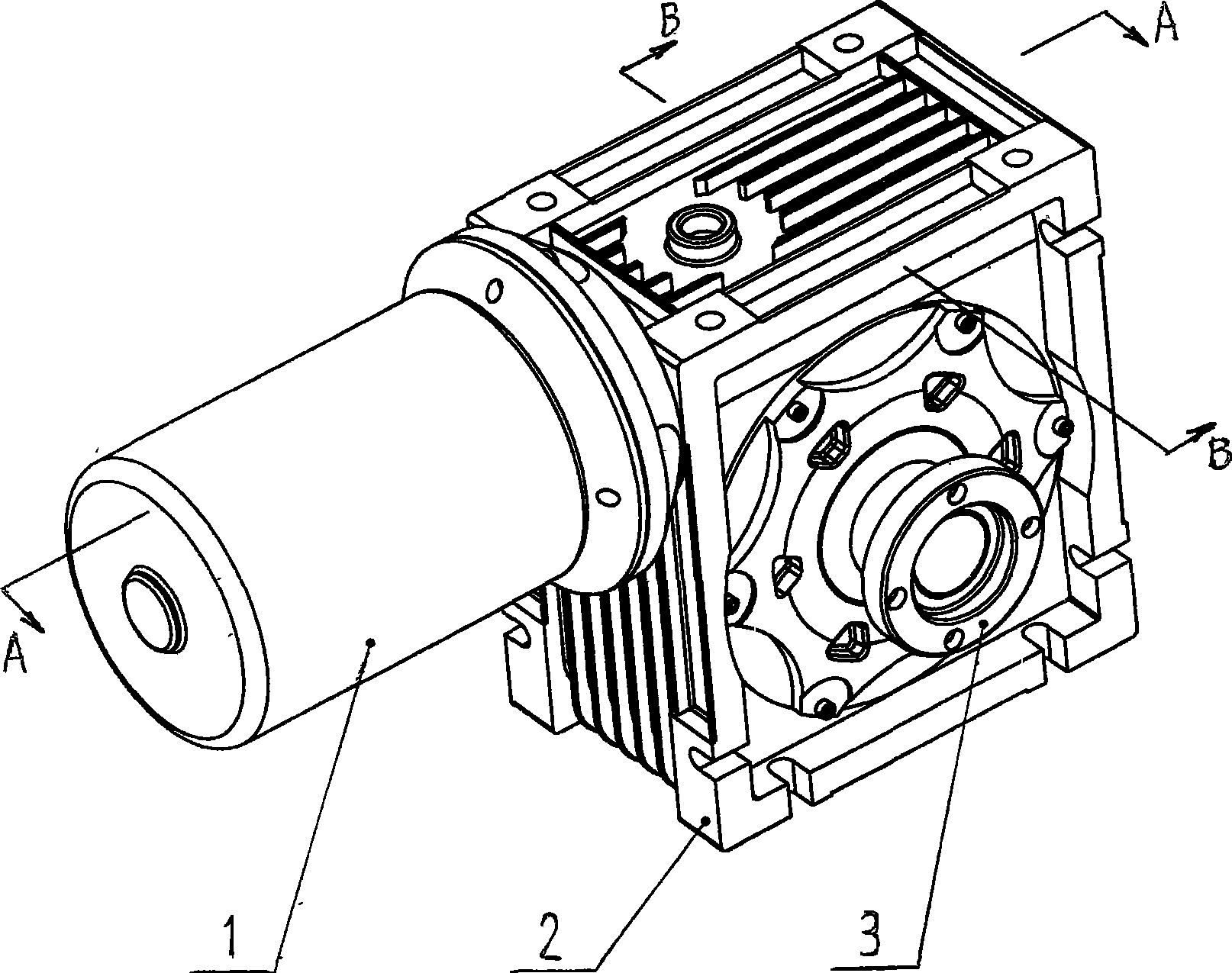
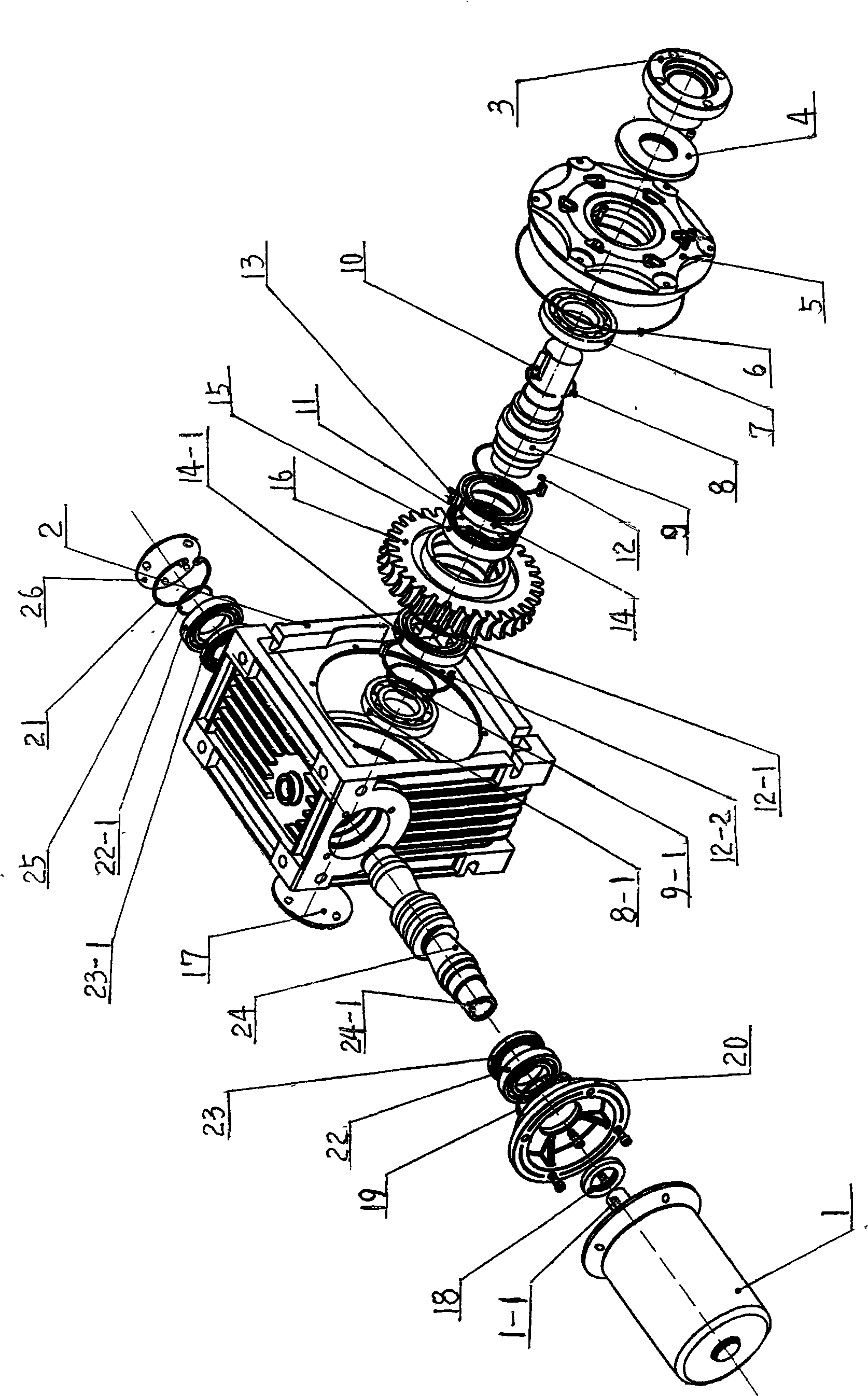
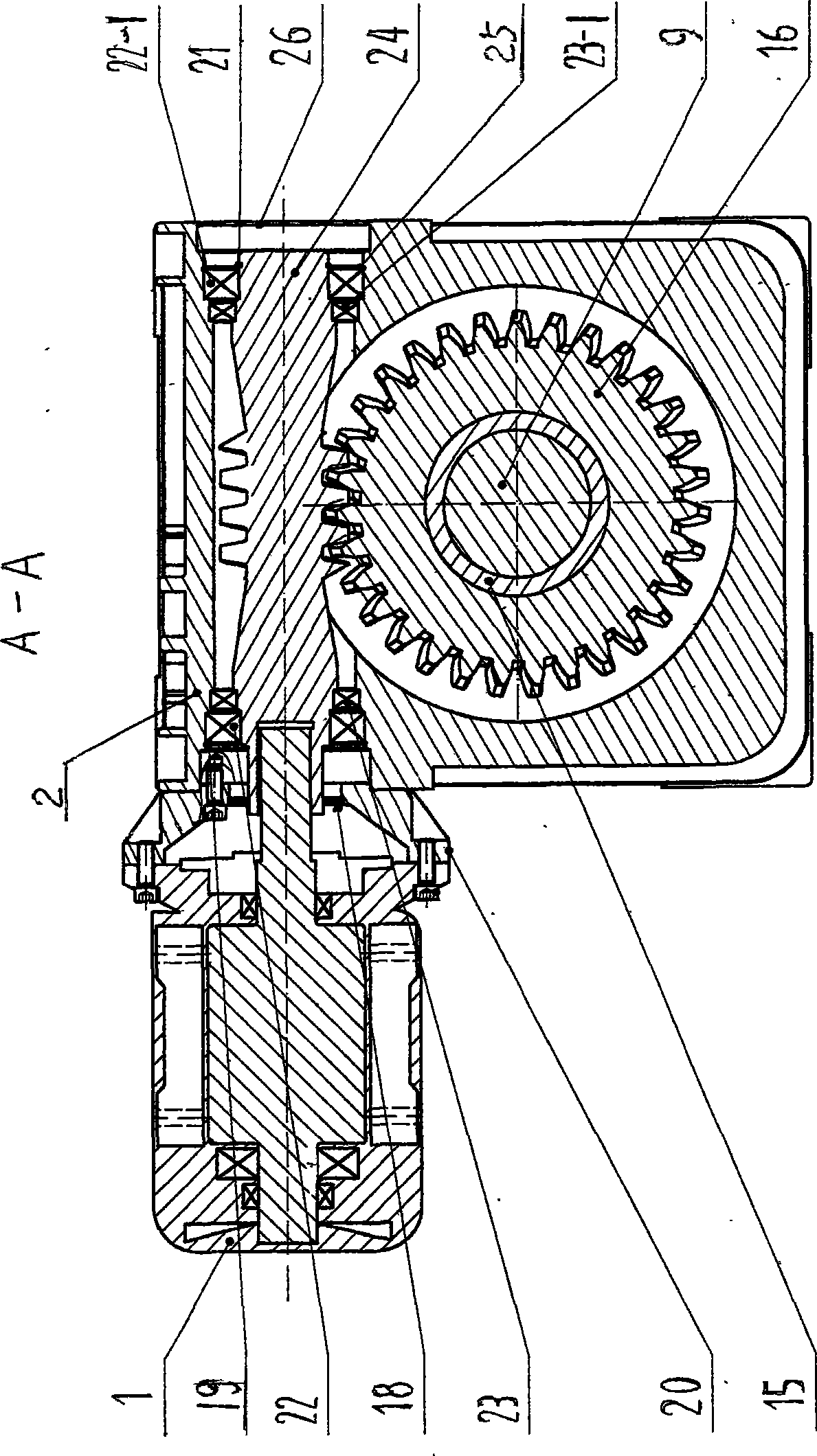
[0012] Examples, see attached Figure 1~4 , a worm 24 is installed in the middle of the upper end of the body 2 of the stepless speed regulation brake of the backstop type hoist. A keyway 24-1 is set in the middle, and a key 1-1 is provided on the motor output shaft to fix it. On the left side of the worm screw 24, a hole with a jumper 19, a worm bearing 22, and an axial bearing 23 are installed, and the left end of the hole with a jumper 19 is equipped with a motor flange 20, and the motor flange 20 uses a worm oil seal 18 and frequency conversion The brake motor 1 is fixed together, and the motor flange 20 is fixed on the body 2 with bolts. On the right side of the worm screw 24, axial bearing two 23-1, worm screw bearing two 22-1, shaft circlip 25, and hole circlip two 21 are arranged successively, and are covered with worm screw end cover 26, and worm screw end cover 26 is used Bolts are fixed on the body 2. The worm gear shaft 9 in the vertical direction at the lower e...


PUM


Abstract

The invention belongs to a mechanical brake system of hoisting equipment, particularly relates to a downstream stepless speed regulating brake of backstop type hoists, comprising a single-directional self-locking type worm and gear speed reducer and a frequency-conversion brake motor (1). The single-directional self-locking type worm and gear speed reducer consists of a body (2), an output coupling (3), front and back end covers (5) and (17) of an output shaft, and a worm end cover (26). The downstream stepless speed regulating brake of the backstop type hoists is characterized in that: a worm (24) is arranged in the axially middle of the upper end in the body (2); a groove is arranged at the center of the left end of the worm (24) and connected with the output shaft of the frequency-conversion brake motor (1); and a keyway (24-1) is arranged in the groove and fixed by a key (1-1) arranged on the output shaft of the motor. With simple operation and accurate control, the downstream stepless speed regulating brake of the backstop type hoists can greatly save electric energy while realizing intelligent control such as failure alarming and automatic stop and the like, reducing heat of equipment, improving operating stability of the equipment and prolonging the service life of the equipment.

Description

technical field [0001] The invention belongs to the mechanical braking system of hoisting and hoisting equipment, in particular to a backstop type stepless speed-regulating brake for the downward movement of a hoist. Background technique [0002] The traditional mechanical braking system of the hoisting motor used in ports and mines directly relies on friction to offset the pulling force of the motor and the gravity of the object when the heavy object is descending. The mechanical friction braking system needs to generate long-term and huge friction to control the downward speed of the lifting motor. Even so, it is difficult to achieve a relatively stable speed control, and the long-term and huge friction will increase the heat of the system. The mechanical wear is serious and the damage is frequent, causing losses such as production stoppage to the enterprise. More advanced energy-consuming brakes, magnetic powder brakes, frequency conversion speed regulation and other con...

Claims


Application Information

Patent Timeline
Patent Type & Authority Applications(China)
IPC IPC(8): B66D1/12B66D1/14B66D1/22B66D5/00
Inventor 李广东
Owner 李广东
Learn More