Mounting and using method of lead core rubber support component with friction pairs
A technology of lead-core rubber bearings and friction pairs, which is applied to bridge parts, bridges, buildings, etc., to achieve the effect of simple component structure and elimination of adverse effects
- Summary
- Abstract
- Description
- Claims
- Application Information
AI Technical Summary
Problems solved by technology
Method used
Image
Examples
Embodiment 1
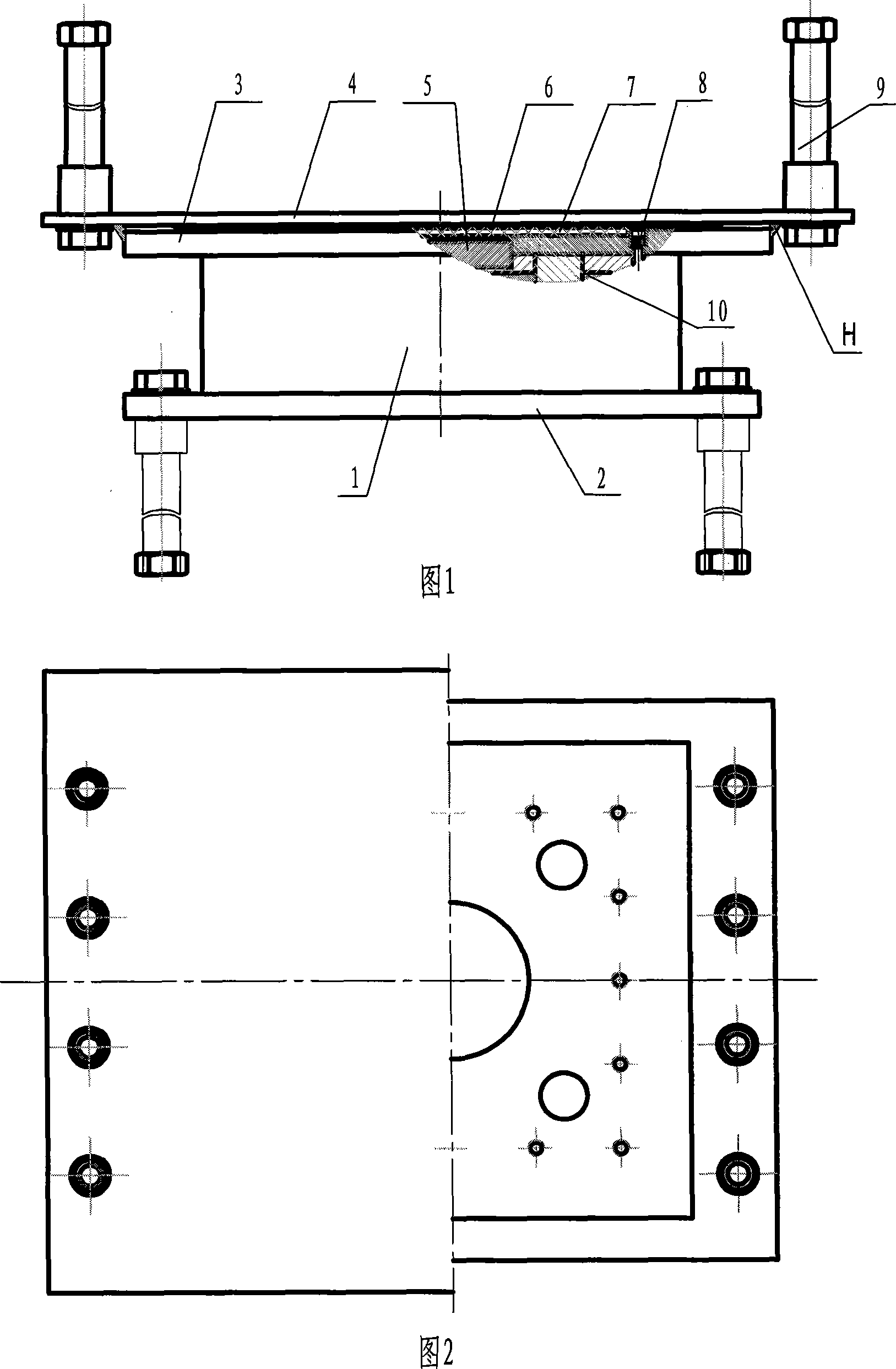
[0039] A lead rubber bearing assembly with one pair of friction pairs, comprising a lead rubber bearing body 1, upper outer connecting steel plates 3, lower outer connecting steel plates 2 and 1 located on the upper and lower ends of the lead rubber bearing body 1 The secondary friction pair M1, the lead rubber bearing body is made of laminated rubber layers, steel plates, etc., and a lead mandrel is poured in the middle. and the shear key 5 are respectively connected with the upper outer connecting steel plate and the lower outer connecting steel plate, and a secondary surface M11 of the friction pair is installed on the outer upper surface of the upper outer connecting steel plate 3 .
[0040] The lead rubber bearing assembly of this structure is generally suitable for the situation where the friction pair is arranged between the top surface of the lead rubber bearing and the bridge beam body. There is a movable steel plate 4 on the bridge beam body, and the other side of the...
Embodiment 2
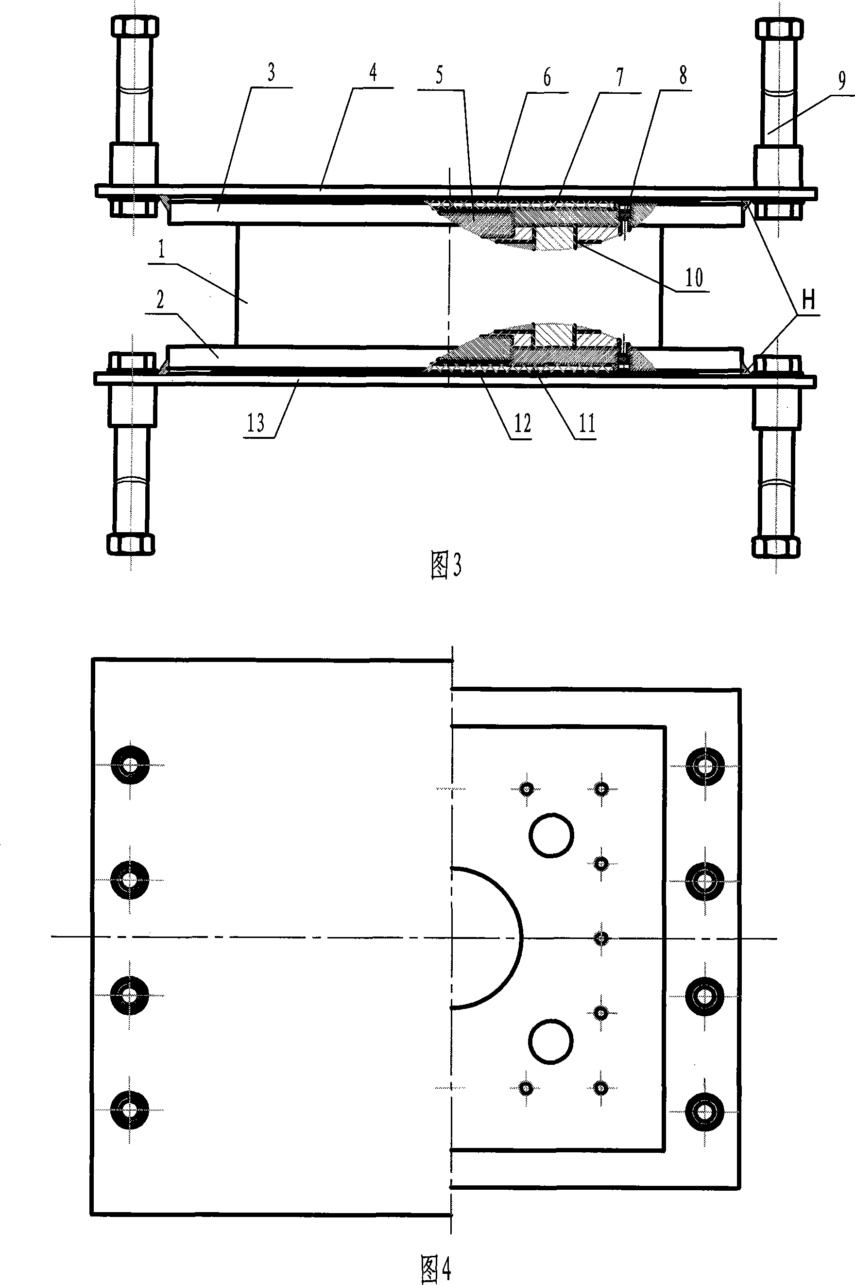
[0043] A lead rubber bearing assembly with two friction pairs, comprising a lead rubber bearing body 1, an upper outer connecting steel plate 3, a lower outer connecting steel plate 2 and two A pair of friction pairs M1 and M2, the lead rubber bearing body is made of rubber layers, steel plates, etc., laminated and bonded, and a lead core rod is poured in the middle, and the upper and lower end surfaces of the lead rubber bearing body 1 pass through The screw 8 and the shear key 5 are respectively connected with the upper outer connecting steel plate 3 and the lower outer connecting steel plate 2, a secondary surface M11 of the friction pair M1 is installed on the outer upper surface of the upper outer connecting steel plate 3, and a secondary surface of the friction pair M2 M21 is installed on the outer lower surface of the lower outer connecting steel plate 2 (see Figure 3 ~ Figure 4 ).
[0044] The top surface and bottom surface of the lead rubber bearing assembly with th...
Embodiment 3
[0048] A method for installing and using the lead rubber bearing assembly with one pair of friction pairs described in Embodiment 1.
[0049] The method is to install the lead rubber bearing assembly with one pair of friction pairs between the bridge girder body and the bridge pier, and install a secondary surface M11 of the friction pair M1 on the lead rubber bearing assembly to connect the steel plate. The upper outer surface; the other secondary surface M12 of the friction pair is installed under the bridge girder body or the movable steel plate of the bridge girder body. Connect and fix with the bridge beam body, connect and fix the lower outer connecting steel plate 2 of the lead rubber bearing assembly with the bridge pier;
[0050] The method includes the following specific steps:
[0051] A. Install the other side of the friction pair of the lead rubber bearing assembly on the bridge beam body: install the friction of the lead rubber bearing assembly under the movable...
PUM
 Abstract
Description
Claims
Application Information
 - R&D
- Intellectual Property
- Life Sciences
- Materials
- Tech Scout
- Unparalleled Data Quality
- Higher Quality Content
- 60% Fewer Hallucinations
Browse by: Latest US Patents, China's latest patents, Technical Efficacy Thesaurus, Application Domain, Technology Topic, Popular Technical Reports.
© 2025 PatSnap. All rights reserved.Legal|Privacy policy|Modern Slavery Act Transparency Statement|Sitemap|About US| Contact US: help@patsnap.com


