Temperature sensor

A technology of temperature sensor and protection tube, used in thermometers, thermometer parts, instruments, etc., can solve the problems of low thermal conductivity of ceramic powder, no ceramic powder, and high response time of temperature sensor, so as to shorten the response time and shorten the response time. Effect

Inactive Publication Date: 2009-07-22
ROBERT BOSCH GMBH
View PDF1 Cites 4 Cited by
  • Summary
  • Abstract
  • Description
  • Claims
  • Application Information

AI Technical Summary

Problems solved by technology

[0003] This has the disadvantage that the ceramic powder is not or very slightly compressed, which means that the ceramic powder can only guarantee a small mechanical protection of the heat-sensit

Method used


Image

  • Temperature sensor
  • Temperature sensor
  • Temperature sensor

Examples


Embodiment Construction

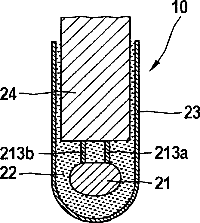
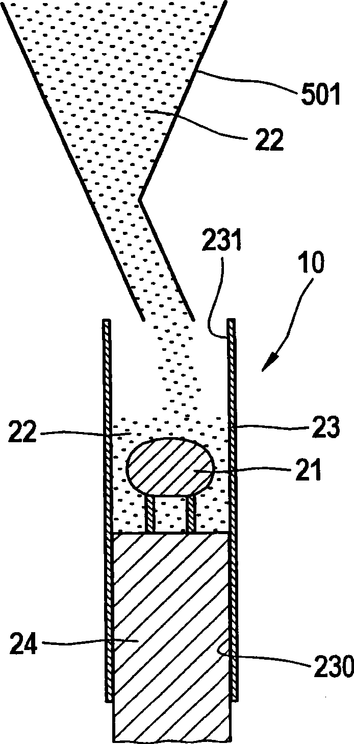
[0019] figure 1 A temperature sensor 10 according to the invention is shown. The temperature sensor 10 includes a thermal sensor 21 , ceramic powder 22 and a protective casing 23 . The thermosensitive element 21 is fixed and insulated in a protective housing 23 by means of compacted ceramic powder 22 . In addition, the temperature sensor 10 also has a closure element 24 whose task is to fill the cross-section of the protective tube 23 and thus seal the protective tube.

[0020] The thermal element 21 is a temperature-dependent resistor, such as an NTC resistor (thermistor with a negative temperature coefficient) or a PTC resistor (thermistor with a positive temperature coefficient).

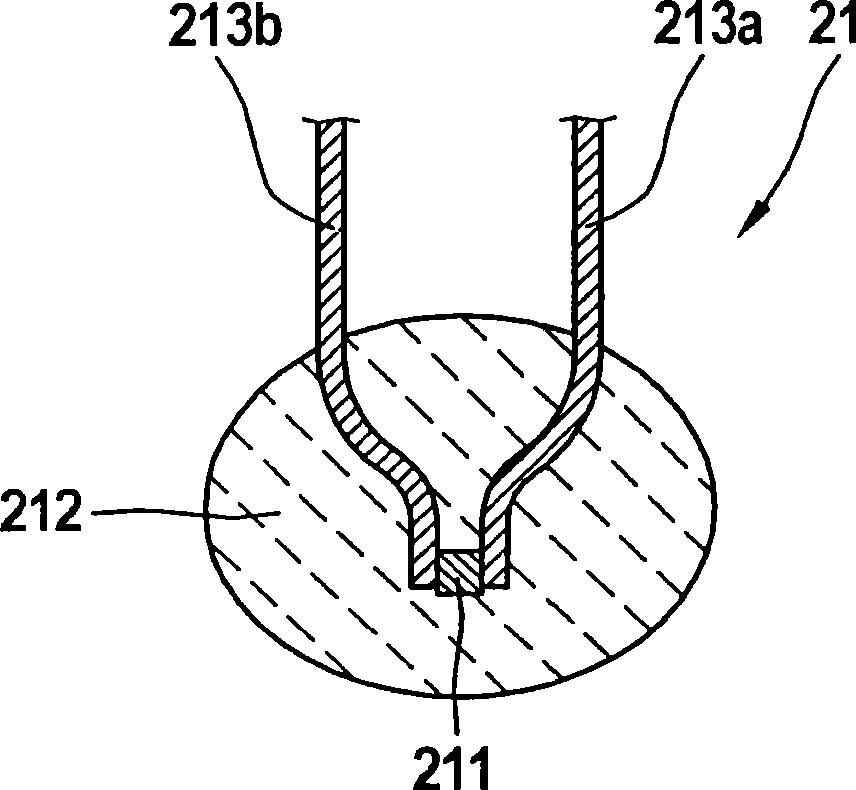
[0021] exist figure 1 In a, the structure of the thermosensitive element 21 is shown. The thermosensitive element 21 has a resistor 211, which includes a semiconductor material such as Fe 2 o 3 , ZnTiO 4 or MgCr 2 o 4 . The resistance element 211 determines the temperature-resistance ch...


PUM


Abstract

The invention relates to a method for manufacturing a temperature sensor (10), wherein the method comprises: inserting ceramic powders (22) into a protection tube (23) and inserting a heat responsive element (21) into the protection tube (23) so as to cause the heat responsive element (21) to be fixed in the protection tube (23) through the ceramic powders (22), wherein the method further comprises: compressing the ceramic powders (22) through at least regionally reducing the circumference of the protection tube (23).

Description

technical field [0001] The present invention relates to a method for manufacturing a temperature sensor, wherein the method has the following steps: filling ceramic powder into a protective tube; inserting a thermosensitive element into the protective tube, wherein the thermosensitive element is activated by the ceramic powder Fixation in protective tube. Background technique [0002] Such a temperature sensor is known, for example, from WO 2005 / 075949 A1 and has a thermosensitive element which is fixed in a protective tube by means of ceramic powder. When manufacturing the temperature sensor described in WO 2005 / 075949 A1, the ceramic powder is compacted into the protective tube together with the thermal element. [0003] This has the disadvantage that the ceramic powder is not or very slightly compressed, which means that the ceramic powder can only guarantee a small mechanical protection of the heat-sensitive element. In addition, due to the extremely low compression of...

Claims


Application Information

Patent Timeline
IPC IPC(8): G01K7/22
CPCG01K1/08
Inventor A·奥普J·施奈德M·罗森兰德
Owner ROBERT BOSCH GMBH
Why Eureka
Try Eureka