
Wireless video automatic monitoring system for pantograph of locomotive

An automatic monitoring system and wireless video technology, applied in the direction of the fault location, etc., can solve the problems of inability to observe the working face of the pantograph, large locomotive shaking, and low image accuracy

Active Publication Date: 2009-07-22
CHINA SHENHUA ENERGY CO LTD +1
View PDF0 Cites 15 Cited by
  • Summary
  • Abstract
  • Description
  • Claims
  • Application Information

AI Technical Summary

Problems solved by technology

[0003] At present, the pantograph monitoring devices developed at home and abroad all adopt the wired transmission method. Since the wired transmission monitoring device needs to lay a large number of cables for signal transmission and control, it is difficult to install and maintain, and it is prone to failure.
Moreover, most of the existing locomotive pantograph monitoring devices are installed on the roof of the locomotive, and such devices need to be installed on each locomotive that needs to be monitored, so the investment is relatively large; During the installation, the camera is at an upward-looking angle, so it is impossible to observe the working face of the pantograph, and because the locomotive shakes greatly, most of the problems of the pantograph and catenary are not easy to be captured by the camera, so the accuracy of the captured images is not high

Method used


Image

  • Wireless video automatic monitoring system for pantograph of locomotive
  • Wireless video automatic monitoring system for pantograph of locomotive
  • Wireless video automatic monitoring system for pantograph of locomotive

Examples


Embodiment Construction

[0019] figure 1 It is a functional block diagram of the wireless video automatic monitoring system for the locomotive pantograph of the present invention. Such as figure 1 As shown, the locomotive pantograph wireless video automatic monitoring system proposed by the present invention includes a remote network monitoring center device 1 and several monitoring point devices 2 . The remote network monitoring center device 1 realizes remote monitoring of the monitoring point device 2 through a wireless network. The quantity of monitoring point equipment 2 can be determined by the user according to the actual situation of needs, installation lines and capital situation.

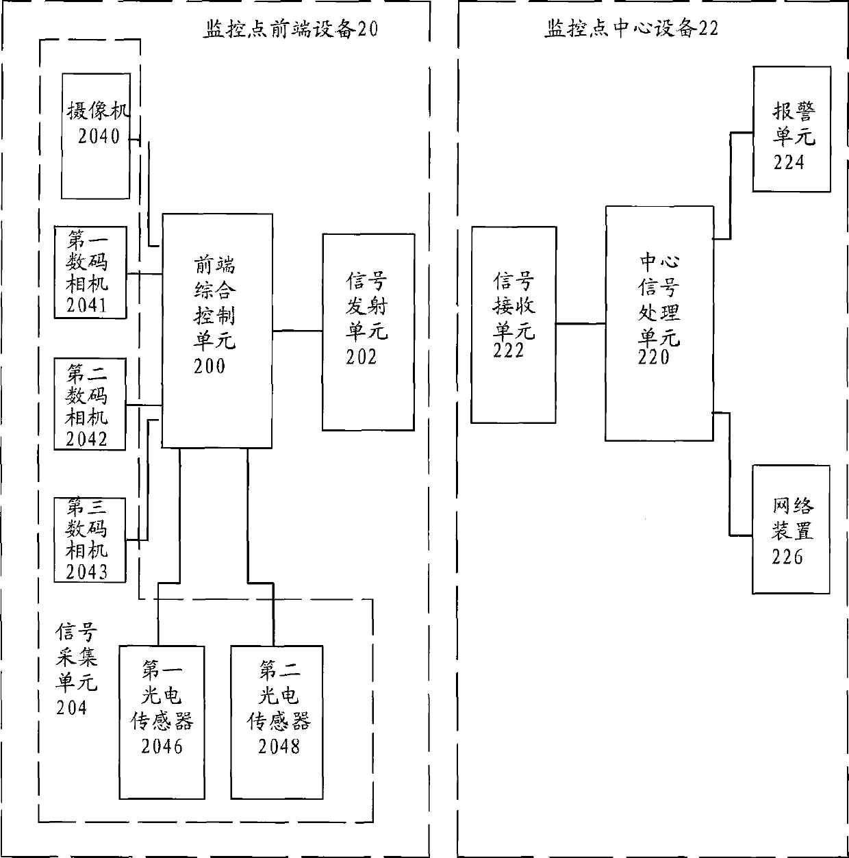
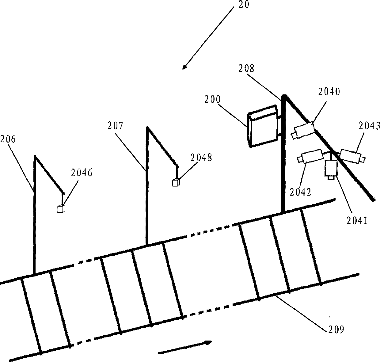
[0020] figure 2 for figure 1 Schematic block diagram of the monitoring point device shown. Such as figure 2 As shown, the monitoring point device 2 includes a monitoring point front-end device 20 and a monitoring point central device 22, and the monitoring point front-end device 20 and the monitoring point...


PUM


Abstract

The invention provides an automatic monitoring system for wireless video of a locomotive pantograph, which comprises a remote network monitoring center device and at least one monitoring point device, wherein, the monitoring point device is connected with the remote network monitoring center device through a wireless network. The automatic monitoring system for the wireless video of the locomotive pantograph can realize real-time monitoring for the pantograph, improves monitoring precision, and simultaneously can also realize remote control function; therefore, the automatic monitoring system is favorable for discovering fault of the pantograph and a contact net in real time.

Description

technical field [0001] The invention relates to an automatic monitoring system, in particular to a wireless video automatic monitoring system for a locomotive pantograph. Background technique [0002] The pantograph is a device for an electric locomotive to receive current from the catenary. Its slide plate is in direct contact with the catenary wire, and receives current from the catenary wire for use by the locomotive. [0003] At present, the pantograph monitoring devices developed at home and abroad all adopt the wired transmission method. Since the wired transmission monitoring device needs to lay a large number of cables for signal transmission and control, it is difficult to install and maintain, and it is prone to failure. Moreover, most of the existing locomotive pantograph monitoring devices are installed on the roof of the locomotive, and such devices need to be installed on each locomotive that needs to be monitored, so the investment is relatively large; During...

Claims


Application Information

Patent Timeline
IPC IPC(8): G01R31/08
Inventor 曹广河于国旺李喆陈维荣张健冯倩
Owner CHINA SHENHUA ENERGY CO LTD
Learn More