
Adaptive determination method for differentiating inrush current and failure current of transformer

A technology of excitation inrush current and fault current, which is applied in the direction of instruments, measuring electronics, electrical components, etc., can solve problems such as slow attenuation, protection delay action, and misoperation of transformer differential protection, so as to accelerate the action speed, avoid misoperation, The effect of ensuring safety

Active Publication Date: 2009-07-22
STATE GRID ZHEJIANG ELECTRIC POWER +1
View PDF0 Cites 31 Cited by
  • Summary
  • Abstract
  • Description
  • Claims
  • Application Information

AI Technical Summary

Problems solved by technology

The response speed of this braking method is fast, and the removal is timely, but it is easy to cause the misoperation of the transformer differential protection
After the differential protection of the transformer operates, the staff have to conduct oil and gas analysis and insulation inspection, which brings a lot of work to the staff, and takes a certain amount of time, prolonging the maintenance time. At the same time, the transformer and the power grid have to undergo re-excitation The impact of inrush current affects the safety of the system and the insulation between transformer coils
[0012] or door brake as Figure 12 As shown, this braking method is relatively reliable, but when the transformer is closed due to an internal fault, the OR gate braking will easily cause the protection to delay action
In addition, the application of long-distance power transmission equipment and static var compensation devices in modern power systems makes the second harmonic content in the transient fault current relatively high, and the attenuation is relatively slow. The use of OR gate braking is not conducive to the protection of rapid fault removal. Affects the security of the system

Method used


Image

  • Adaptive determination method for differentiating inrush current and failure current of transformer
  • Adaptive determination method for differentiating inrush current and failure current of transformer
  • Adaptive determination method for differentiating inrush current and failure current of transformer

Examples


Embodiment Construction

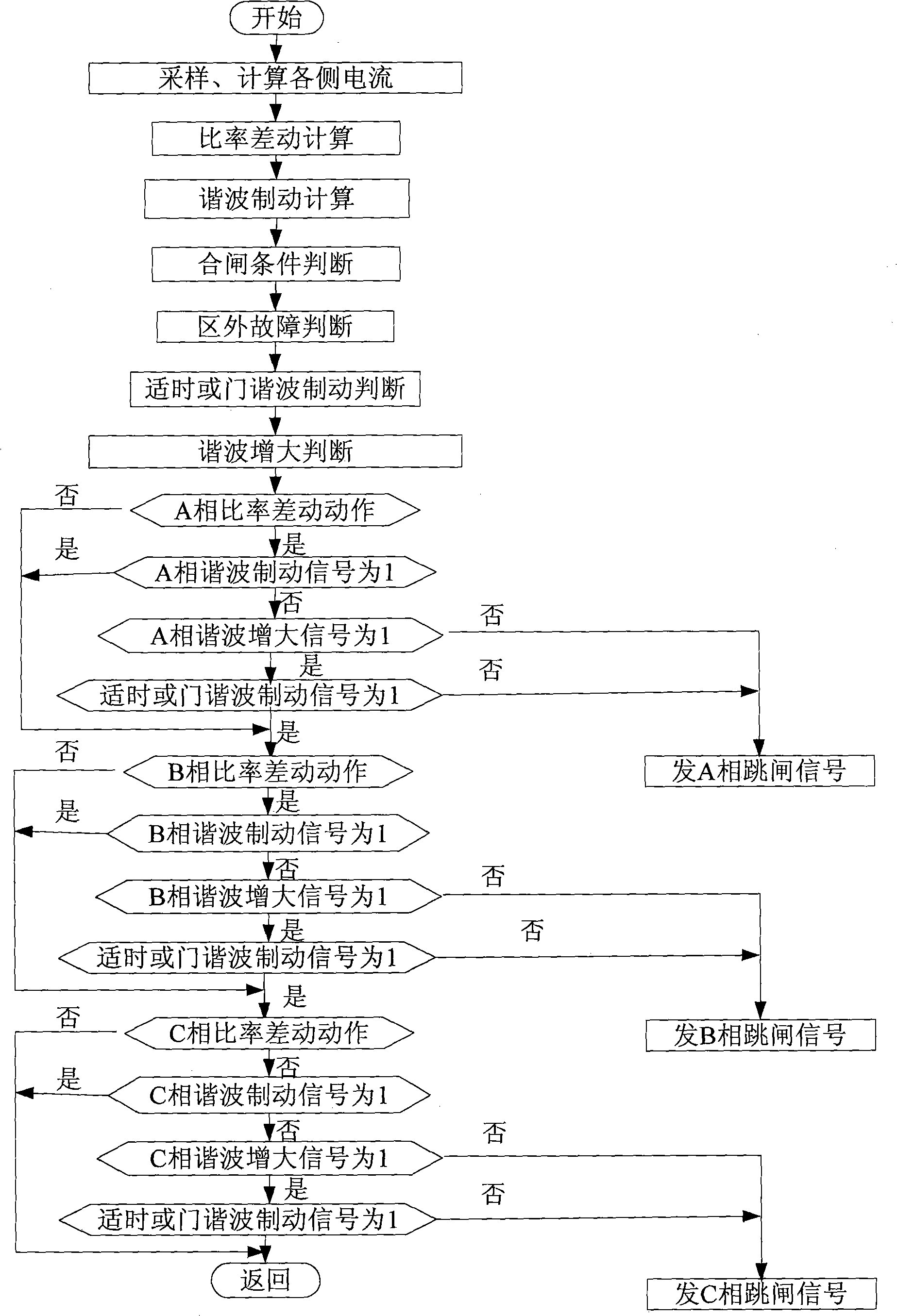
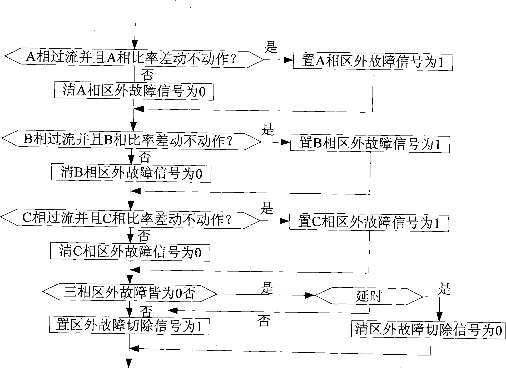
[0041] Such as figure 1 The self-adaptive judgment method for distinguishing transformer excitation inrush current and fault current shown in the figure is sequentially through sampling calculation of each side current, ratio differential calculation, harmonic braking calculation, closing condition judgment, out-of-area fault judgment, timely OR gate harmonic Brake judgment and harmonic increase judgment, and then obtain the final judgment result of each phase according to the ratio differential, harmonic braking signal, harmonic increase signal and timely OR gate harmonic braking signal of each phase, to Decide whether to trip or not.

[0042] The generation process of the closing condition signal and the judgment module are as follows: figure 2 , 6 As shown, the delay is generally set to more than 1 second. When there is no current on each side, the no-current signal is set to logic 1. When there is current on any side, the no-current signal is immediately set to logic 0. ...


PUM


Abstract

The invention relates to the technology of relay protection, in particular to an adaptive judging method for distinguishing transformer excitation surge current from failure current; the defects of easily causing false action of transformer differential protection and delayed protection exist in the prior art; in the invention, sampling calculation of current on each side, ratio differential calculation, harmonic braking calculation, switching condition judgment, external failure judgment, timely or gate harmonic braking judgment and harmonic increment judgment are carried out in turn, and then final judgment result of each phase is obtained according to the ratio differential, harmonic braking signal, harmonic increment signal and timely or gate harmonic braking signal of each phase so that whether to have tripping operation is determined. The method avoids the generation of false action, saves unnecessary overhauling, and also guarantees the security of system.

Description

【Technical field】 [0001] The invention relates to a relay protection technology, in particular to a method for distinguishing transformer excitation inrush current and fault current and then deciding whether to trip. 【Background technique】 [0002] In order to ensure the safe operation of power systems and power transformers, relay protection devices are generally installed on them. Once a fault is found in the transformer area, the transformer will be removed from the system quickly to avoid serious consequences. However, during the operation of the transformer, there will be an excitation inrush current phenomenon, and the high current signal generated by it is often mistaken for a fault current and cause a trip, resulting in unnecessary losses. Therefore, it is necessary to distinguish the excitation inrush current from the fault current by collecting relevant data of the transformer. And brake the trip that may be caused by the excitation inrush current. [0003] There ...

Claims


Application Information

Patent Timeline
IPC IPC(8): H02H7/04G01R31/00
Inventor 盛海华徐习东张怀宇朱炳铨裘愉涛方愉冬
Owner STATE GRID ZHEJIANG ELECTRIC POWER
Learn More