Switch comprising a coupling for fixing to an actuating device

A technology for operating devices and clutches, applied to electric switches, substations/switch layout details, contact operating parts, etc., can solve problems such as inability to protect edge clutches

Active Publication Date: 2009-07-22
SIEMENS AG
View PDF1 Cites 4 Cited by
  • Summary
  • Abstract
  • Description
  • Claims
  • Application Information

AI Technical Summary

Problems solved by technology

This involves a clutch mechanically connecting the actuating device with the switching element, and the effect of undesired forces is conducted through a front panel, which means that the edge clutches will not be protected from any undesired damage to the transmitted forces

Method used


Image

  • Switch comprising a coupling for fixing to an actuating device
  • Switch comprising a coupling for fixing to an actuating device
  • Switch comprising a coupling for fixing to an actuating device

Examples


Embodiment Construction

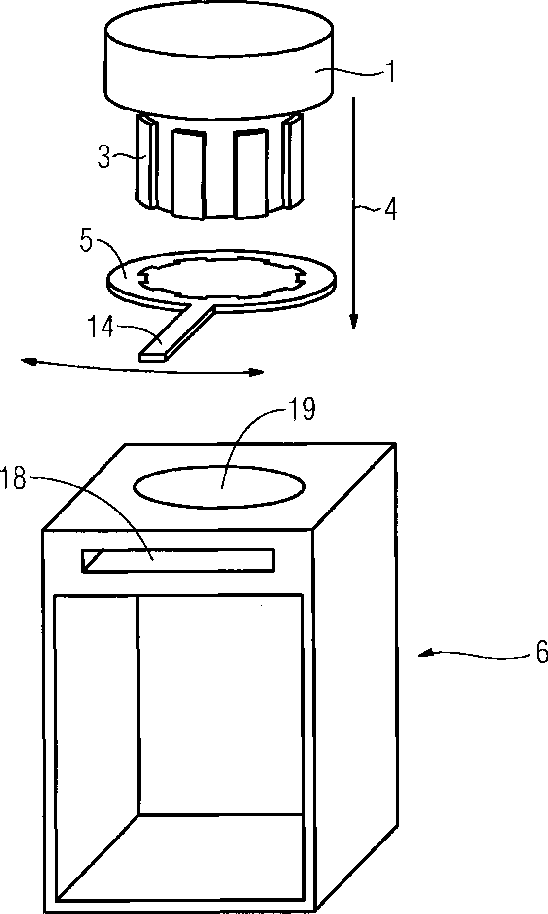
[0035] figure 1 The components of a position switch or safety switch are shown in a disassembled state. The components involved are a housing 6 , a locking ring 4 and a drive 1 with the second flange 3 . The steering mechanism of the drive device 1 is not depicted, and the drawing focuses on the drive head 1 .

[0036] In this exemplary embodiment, the locking ring 4 is designed to be pushed into a slot 18 on the housing 6 . In the inserted position, the locking ring 4 can be in an unlocked position and a locked position, and during the unlocking process, the third flange 5 of the locking ring 4 is aligned with the first flange (not shown here) of the housing. ), or at least partially misalign the first flange during latching.

[0037] The housing 6 is mountable in the use position and is intended to receive a switching element. In the unlocked position, the drive device 1 can be lowered along the second flange 3 into the opening 19 of the housing. At the same time as the...


PUM


Abstract

The invention relates to a switch, especially a position switch, comprising a coupling for fixing a drive head to the base of a locking ring. The aim of the invention is to find a technical solution to ensure a reliable operation of the switch and to simultaneously guide potentially damaging force effects from the drive head via the coupling to the housing of the switch. To this end, first, second and third noses are used, which have an arrangement or shape enabling an essentially non-positive force transmission to be carried out. Furthermore, optimum handling by the user is ensured, especially for the replacement of the drive head.

Description

technical field [0001] The invention relates to a switch having a clutch for fastening to an actuating device, the clutch having a first flange for an exact fit plug-in fastening and a locking ring The second flange of the device, while the locking ring has a third flange formed on the inner circumference for locking the fixing device. Background technique [0002] Such a switch is generally an electromechanical switching device and is widely used, for example, as a position switch or safety switch in the fields of automation technology, plant engineering and building technology. [0003] One of the uses of these switches or switching devices is to monitor protective devices, such as safety gates and safety barriers, or also to monitor the movement of machine parts. [0004] Position switches and safety switches essentially consist of a switch housing to which is connected an actuating device, which is also referred to as a drive device or drive head. The operating device ...

Claims


Application Information

Patent Timeline
Patent Type & Authority Applications(China)
IPC IPC(8): H02B1/44H01H13/14
CPCH01H3/12H01H13/14H02B1/044
Inventor 维尔纳·普里约阿希姆·塞德尔
Owner SIEMENS AG
Why Eureka
Try Eureka