Surge voltage suppressor

a surge voltage and suppressor technology, applied in the direction of overvoltage protection resistors, emergency protective arrangements for limiting excess voltage/current, dc-ac conversion without reversal, etc., can solve the problems of reducing the insulation effect of the winding, requiring a large space for setting the filter, and entail high cost, so as to prevent the effect of oil or chips being cut, absorbing only surge energy without wasting energy, and securely absorbing surge energy

Inactive Publication Date: 2005-03-03
FANUC LTD
View PDF17 Cites 2 Cited by
  • Summary
  • Abstract
  • Description
  • Claims
  • Application Information

AI Technical Summary

Benefits of technology

[0013] The semiconductor surge absorbing devices are mounted on a printed board housed in a hermetically sealed case. Thus, cutting oil or chips are prevented from adhering to the devices or the printed board. Furthermore, the case is used doubling as a terminal box attached to the motor.
[0014] According to the present invention, there may be provided a compact surge voltage suppressor that can absorb only surge energy without wasting energy. According to the invention, surge energy can be securely absorbed with use of a simple construction that requires only a narrow setting space, and the effect of insulation between the phases of the motor and between the ground and the phases can be prevented from lowering.

Problems solved by technology

These surge voltages inevitably lower the effect of insulation between the windings and between the ground and the windings.
According to the method in which the surge voltages are suppressed by the filter that is composed of the reactor and the capacitor, however, setting the filter requires a wide space and entails high cost.

Method used


Image

  • Surge voltage suppressor
  • Surge voltage suppressor
  • Surge voltage suppressor

Examples


first embodiment

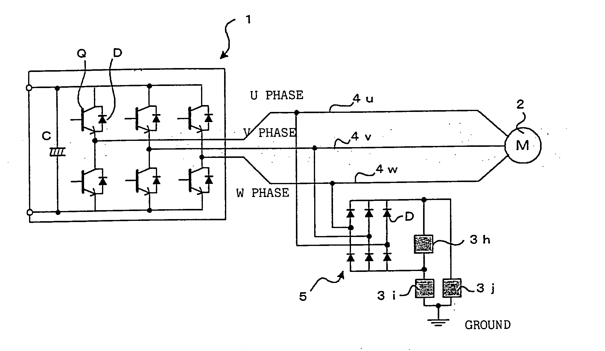
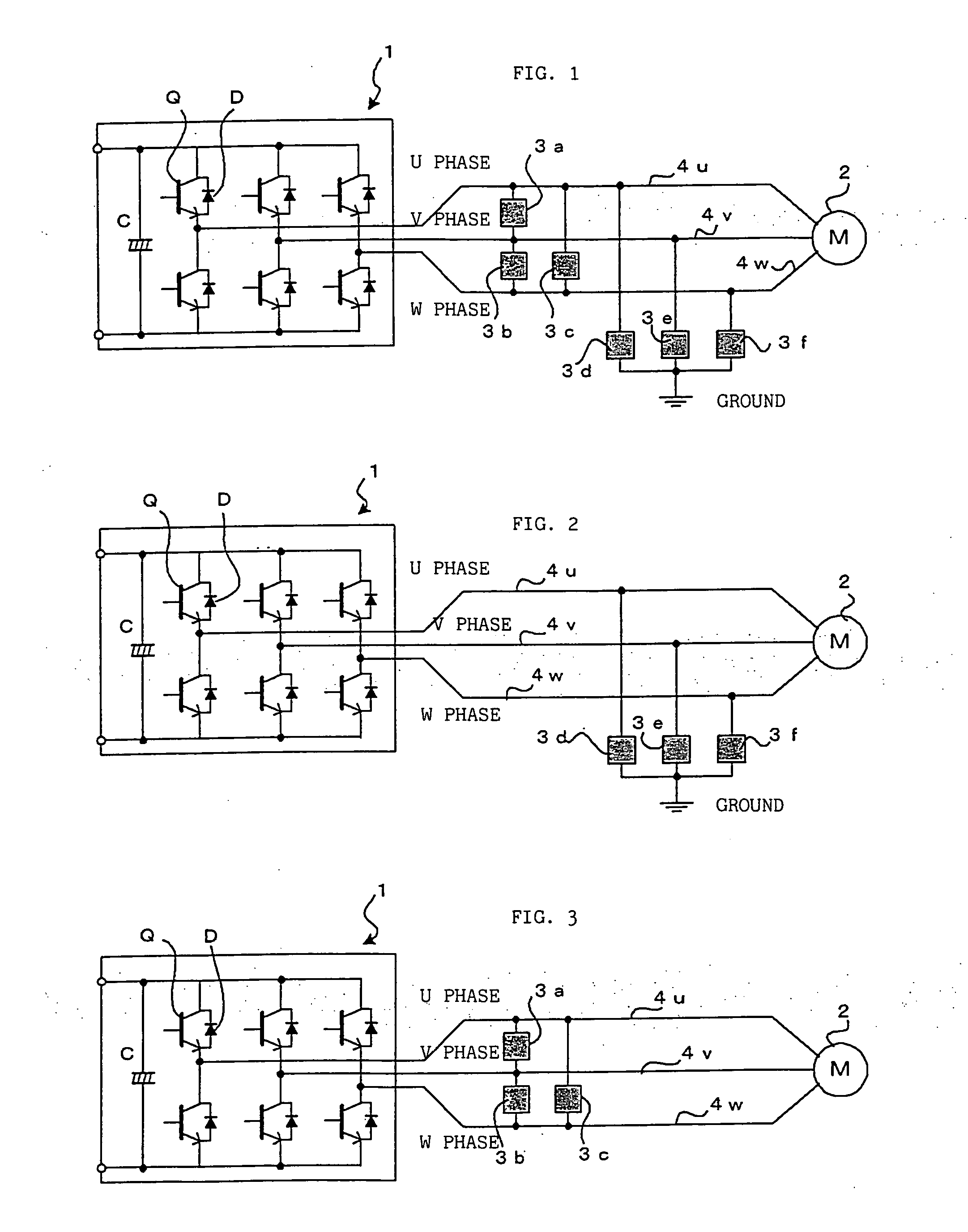
[0025]FIG. 1 is a block diagram showing principal parts according to the invention.

[0026] Numeral 1 denotes a conventional inverter that converts DC voltage into AC voltage by PWM control. Parallel-connected sets of switching elements Q, such as power transistors, and diodes D are connected in series between positive and negative terminals of a DC power supply for the U, V and W phases. Outputs from the inverter 1 for the individual phases are fetched from series-connection nodes of the parallel-connected sets of switching elements Q and diodes D, and delivered to U-, V- and W-phase windings of a motor 2 by means of power lines 4u, 4v and 4w, individually. Symbol C in the inverter 1 designates a capacitor of the DC power supply.

[0027] Semiconductor surge absorbing devises 3 (3a to 3f) are connected between the phases and between the ground and the phases. They have characteristics such that current flows through them to clamp voltage when the voltage reaches a given or higher value...

second embodiment

[0033]FIG. 2 is a block diagram showing principal parts according to the invention.

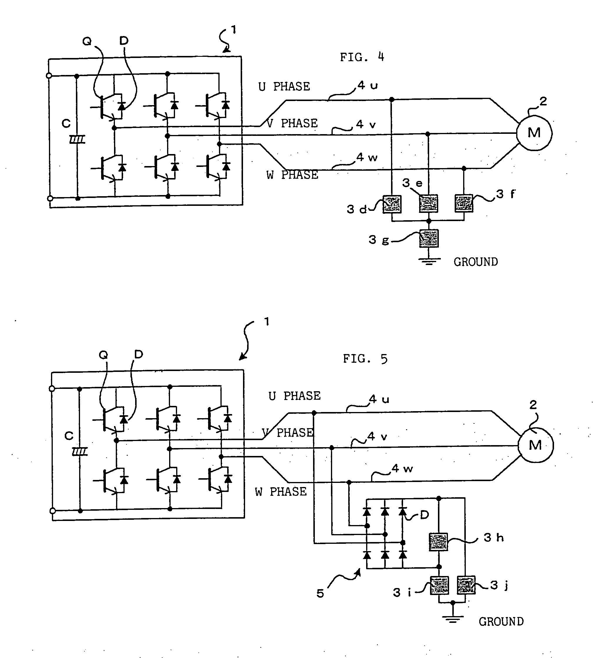
[0034] According to this second embodiment, the semiconductor surge absorbing devices 3a, 3b and 3c between the power lines 4u, 4v and 4w for the individual phases according to the first embodiment shown in FIG. 1 are omitted, and semiconductor surge absorbing devices 3d, 3e and 3f are arranged only between the ground and the power lines 4u, 4v and 4w. If voltages between the ground and the power lines 4u, 4v and 4w exceed the clamping voltages of the semiconductor surge absorbing devices 3d, 3e and 3f, the devices 3d, 3e and 3f are energized and absorb the surge voltages.

third embodiment

[0035]FIG. 3 is a block diagram showing principal parts according to the invention.

[0036] According to this third embodiment, the semiconductor surge absorbing devices 3d, 3e and 3f between the ground and the power lines 4u, 4v and 4w for the individual phases according to the first embodiment shown in FIG. 1 are omitted, and semiconductor surge absorbing devices 3a, 3b and 3c are arranged only between the power lines 4u, 4v and 4w. If voltages between the phases are increased above the clamping voltages, the semiconductor surge absorbing devices 3a, 3b and 3c are energized and absorb the surge voltages.

[0037] The first to third embodiments may be used alternatively, depending on the specifications and characteristics of the motor and the like.


PUM


Abstract

Semiconductor surge absorbing devices are connected individually between power lines for the U, V and W phases, which connect an inverter and a motor, and between the ground and the power lines. The absorbing devices are adapted to be energized to clamp voltages between opposite terminals thereof when the voltages are higher than a given value.

Description

BACKGROUND OF THE INVENTION [0001] 1. Field of the Invention [0002] The present invention relates to a surge voltage suppressor for suppressing surge voltages that are generated in a motor when the motor is PWM-controlled by means of an inverter. [0003] 2. Description of the Related Art [0004] In drivingly controlling a motor by PWM (pulse width modulation) control using an inverter, DC voltage is converted into AC voltage by switching power transistors or other switching elements for PWM control, and the AC voltage is applied to windings for the individual phases of the motor. [0005] In subjecting the motor to PWM control, the DC voltage is on-off controlled with the switching elements. If power lines for connection with the motor are long, their inductance increases so that surge voltages are generated between three-phase windings in the motor and between the ground and the windings. These surge voltages inevitably lower the effect of insulation between the windings and between th...

Claims


Application Information

Patent Timeline
Patent Type & Authority Applications(United States)
IPC IPC(8): H02H7/08H02H9/04H02M1/00H02M7/48
CPCH02H9/042H02H7/0838
Inventor MATSUBARA, SHUNSUKEKIMIJIMA, MASAMIYAMADA, YUUICHI
Owner FANUC LTD
Why Eureka
Try Eureka