
Femoral compression haemostat

A technology of oppressing hemostasis and femoral artery, which is applied in the field of medical devices and can solve the problems of patients' discomfort and difficulty in controlling pressure

Inactive Publication Date: 2009-07-29
王晓舟
View PDF1 Cites 4 Cited by
  • Summary
  • Abstract
  • Description
  • Claims
  • Application Information

AI Technical Summary

Problems solved by technology

[0003] The purpose of the present invention is to overcome the shortcomings of the existing femoral artery compression hemostat that the patient feels uncomfortable and the pressure is not easy to grasp, and propose an improved femoral artery compression hemostat

Method used


Image

  • Femoral compression haemostat

Examples


Embodiment Construction

[0009] The embodiments will be further described below with reference to the accompanying drawings.

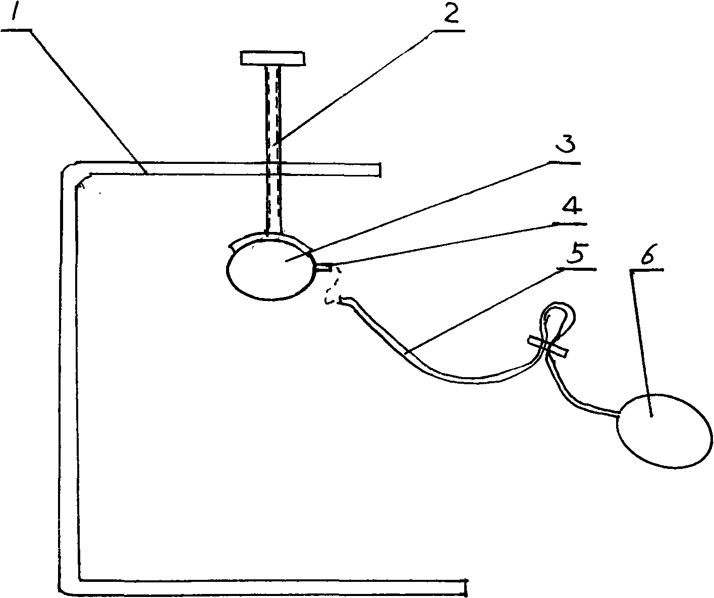
[0010] Such as figure 1 As shown, the compression hemostat of the present invention is connected with a height-adjustable pressure rod 2 on the top of a "匚" type bracket 1, and an elastic liquid storage bag with a nozzle 3 is placed on the bottom end of the pressure rod 2 3. A liquid injection tube 5 is inserted into the mouth of the nozzle 3, and a hand suction ball 6 is connected to the liquid injection tube 5.

[0011] When in use, press the liquid into the liquid storage bag 3 by pinching the suction ball 6 and the liquid injection tube 5, then fold the liquid injection tube 5 in half and clamp it with a clip, and the liquid storage bag 3 is pressed on the hemostasis point by pressure, thereby achieving hemostasis the goal of.


PUM


Abstract

The invention discloses a femoral artery compression hemostat, which is characterized in that the top of a bracket is connected with a height adjustable pressure lever, the bottom end of the pressure lever is sleeved with an elastic liquid storage bag, one side of the liquid storage bag is provided with a nozzle, and an injection tube is inserted in the nozzle. When the femoral artery compression hemostat is used, liquid is injected into the injection tube through modes of holding a pipet bulb or a liquid injector or other injection modes; and after the liquid is communicated with the elastic liquid storage bag, the liquid is pressed into the liquid storage bag, and the injection tube is folded in half and clipped by a clip to prevent the liquid from flowing back. The liquid storage bag is pressed on a hemostasis point to achieve the aim of hemostasis. Because the liquid storage bag has elasticity and small heat absorption coefficient, the pressure is easily controlled during liquid injection, and a patient feels comfortable.

Description

technical field [0001] The present invention relates to medical devices. Background technique [0002] At present, when a doctor performs interventional therapy on a patient, it is sometimes necessary to puncture the femoral artery in the patient's thigh to implement the interventional operation. After the interventional operation, it is necessary to compress the puncture point of the patient to stop bleeding. Several current hemostats (such as patent No. ZL200520130319.2) all connect an adjustable height-adjustable pressure rod (generally with a screw) on the top of the inverted "L" type bracket or "匚" type bracket, and the bottom of the pressure rod The end is connected with a strip-type pressure block with a notch. Although it is conducive to the extraction of the catheter and can stop bleeding immediately, the pressure of the bar-type briquetting block on the patient's skin is rigid, the patient is uncomfortable, and the size of the pressure is difficult to control. ...

Claims


Application Information

Patent Timeline
Patent Type & Authority Applications(China)
IPC IPC(8): A61B17/12
Inventor 王晓舟
Owner 王晓舟
Learn More