

Light barrier
一种光栅栏、光路的技术,应用在光栅栏领域,能够解决错误反射、安全级别低、范围限制等问题
- Summary
- Abstract
- Description
- Claims
- Application Information
AI Technical Summary
Problems solved by technology
Method used
Image

Examples
Embodiment Construction
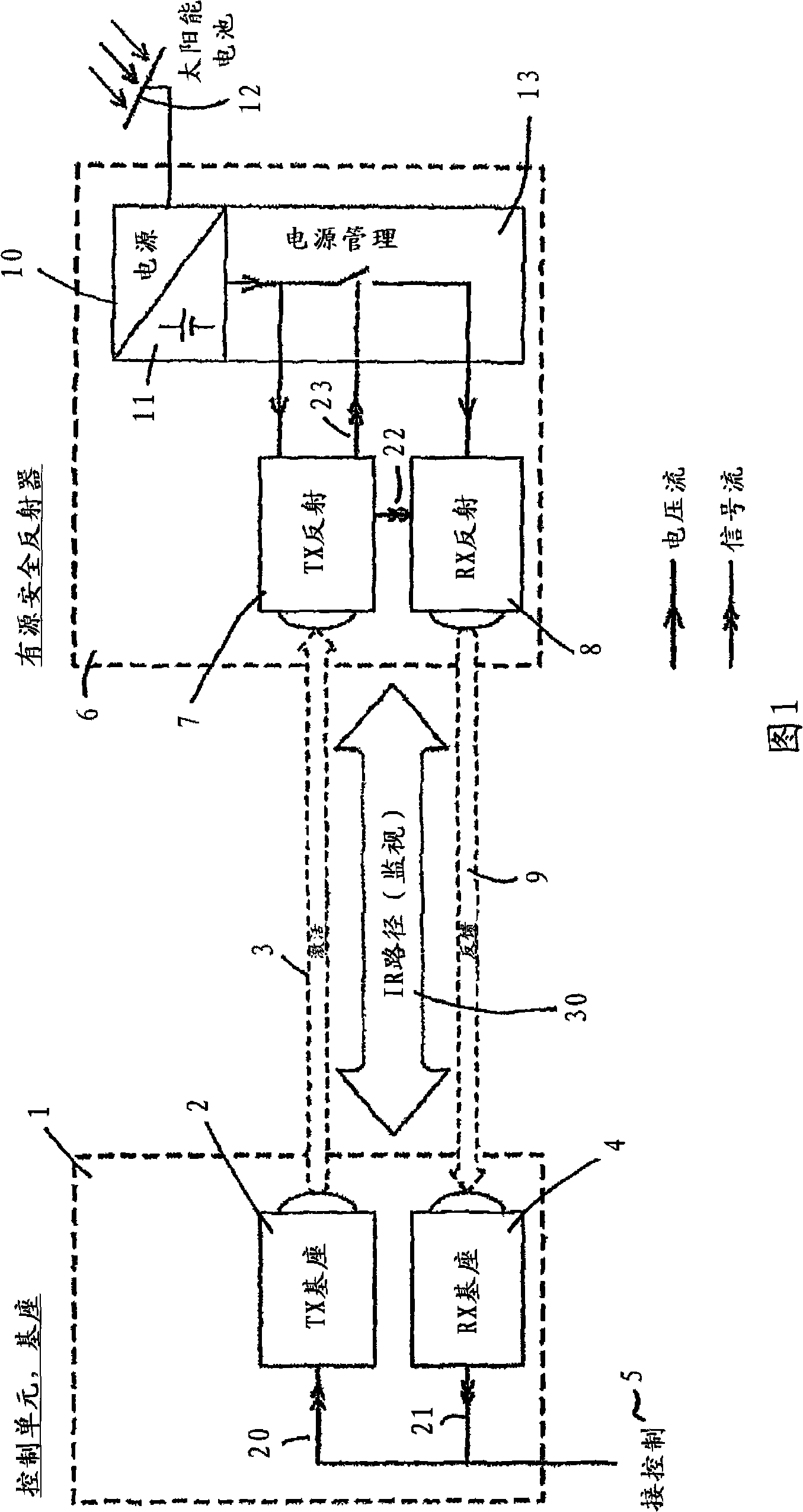
[0028] FIG. 1 shows a schematic diagram of a light barrier according to the invention for monitoring a light path 30 . The base assembly 1 has a first transmitter 2 that emits an optical signal 3 along the light path to be monitored and a first receiver 4 that generates an output signal for control 5 . The base assembly 1 is made as a base device integrating a first transmitter 2 and a first receiver 4 . They thus form a unit.
[0029] Instead of passive reflectors, now, according to the invention, the light barrier of the invention has an active reflector assembly 6 with a second receiver 7 and a second emitter 8, wherein the second receiver 7 is used to receive the optical signal 3 emitted by the first transmitter 2, and the second transmitter 8 is used to transmit a feedback signal 9 according to the received signal. The active reflector assembly 6 also forms a unit in which the second receiver 7 and the second emitter 8 are integrated.
[0030] In the light barrier acco...
PUM
 Abstract
Description
Claims
Application Information