

Valve unit, electro-pneumatic brake control device having a valve unit of said type for controlling a parking brake, vehicle brake system having a brake control device of said type and vehicle having
A technology of parking brake and brake control, applied in the direction of manual start device, valve operation/release device, brake, etc., to achieve the effect of improving switch performance, fewer components, and compact structure
- Summary
- Abstract
- Description
- Claims
- Application Information
AI Technical Summary
Problems solved by technology
Method used
Image

Examples
Embodiment Construction
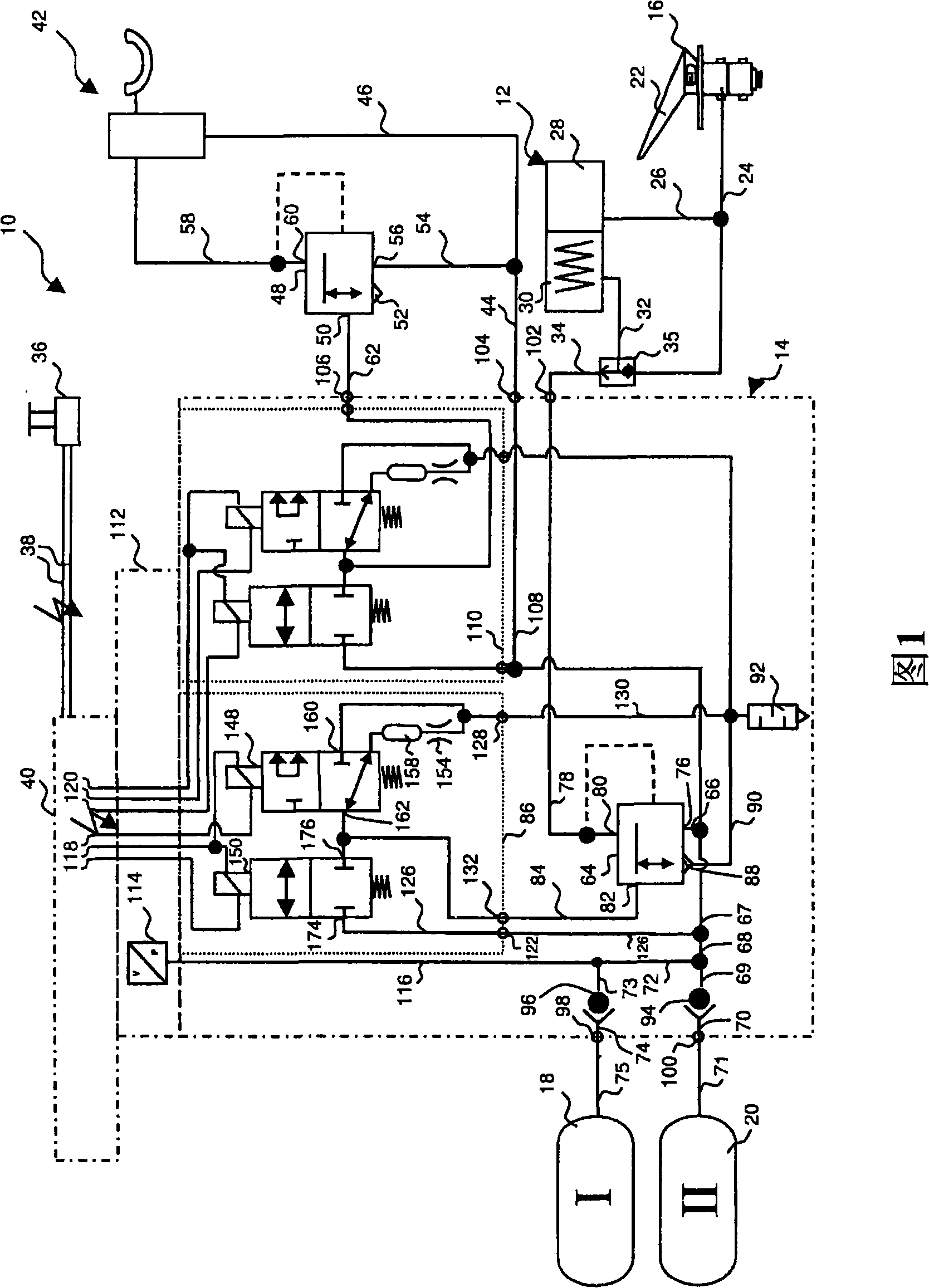
[0030] FIG. 1 schematically shows a part of a compressed air brake system 10 of a motor vehicle, in particular an electropneumatic brake control device for controlling the parking brake of the motor vehicle. Such compressed air brake systems are used, for example, in commercial vehicles, trucks or coaches. Such a braking system is used in particular in a vehicle traction system consisting of a tractor and a trailer.
[0031] FIG. 1 shows only the components of the brake system 10 that are most important for understanding the invention. The braking system 10 is electrically controlled, that is to say the braking pressure metering to the brake cylinders for actuating the wheel brakes arranged on the wheels of the vehicle is controlled by means of electrical or electronic control elements. The brake cylinder is partially or completely formed as a combined service and spring-charged brake cylinder 12 (only one such brake cylinder is shown in FIG. 1 for reasons of clarity), wherei...
PUM
 Abstract
Description
Claims
Application Information