
Heating apparatus and glass manufacturing method

A heating device and glass manufacturing technology, applied in glass manufacturing equipment, glass pressing, manufacturing tools, etc., can solve the problems of glass product optical property degradation, streaks, uneven temperature distribution of molten glass, etc.

Inactive Publication Date: 2009-08-05
OHARA
View PDF10 Cites 0 Cited by
  • Summary
  • Abstract
  • Description
  • Claims
  • Application Information

AI Technical Summary

Problems solved by technology

Therefore, the temperature distribution in the molten glass flowing out of the channel becomes non-uniform, which causes streaks
In addition, the glass is crystallized, which will also lead to a decrease in the optical properties of the manufactured glass products.

Method used


Image

  • Heating apparatus and glass manufacturing method
  • Heating apparatus and glass manufacturing method
  • Heating apparatus and glass manufacturing method

Examples


Embodiment Construction

[0062] In order to further explain the technical means and effects that the present invention adopts to achieve the intended purpose of the invention, the specific implementation methods, The method, steps, structure, features and effects thereof are described in detail below.

[0063] Hereinafter, an embodiment structure of the present invention will be described with reference to the drawings. In addition, in the description of each embodiment structure other than the first embodiment structure, the same reference numerals are used for the same parts as the first embodiment structure, and related descriptions are omitted.

[0064]

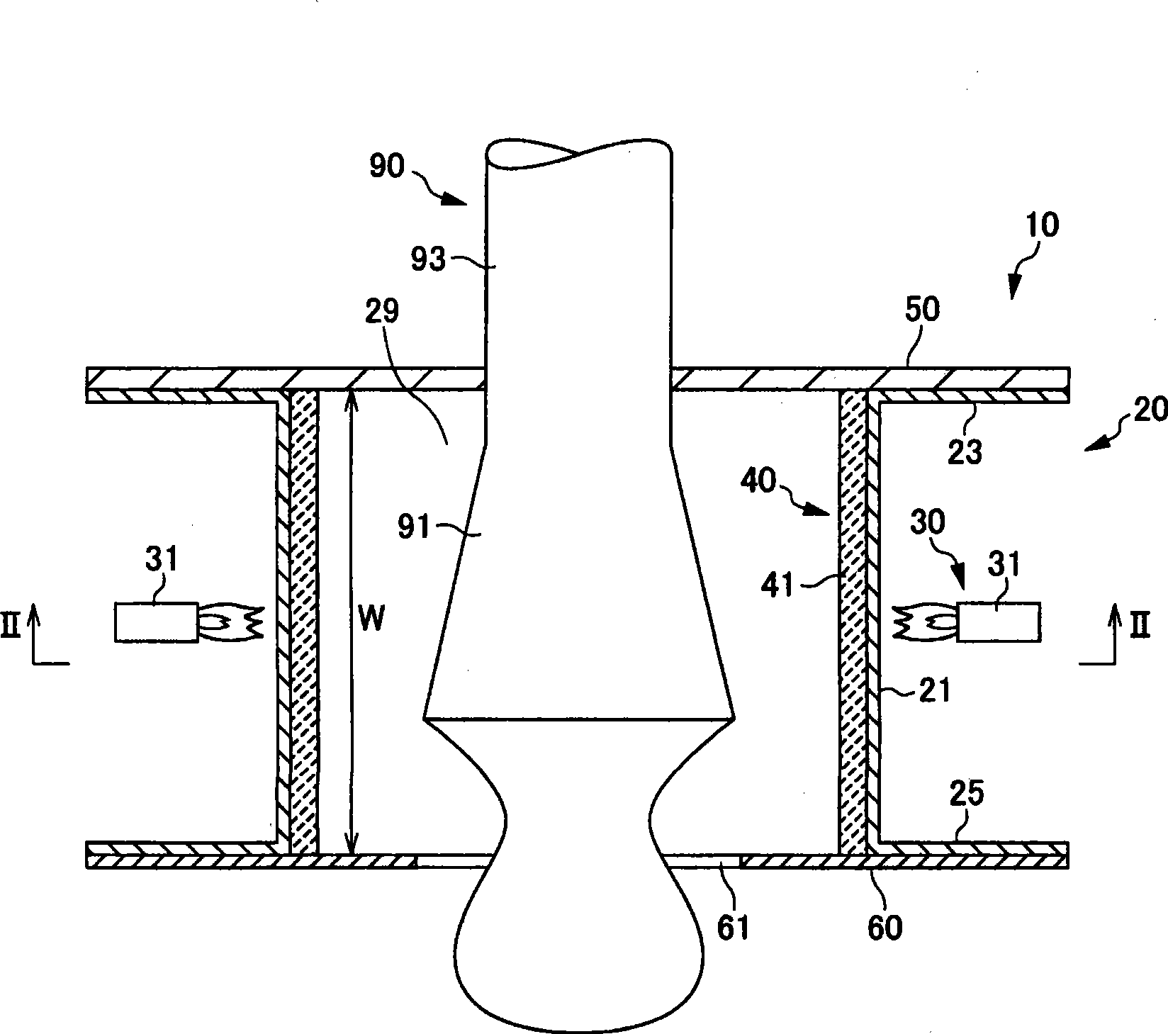
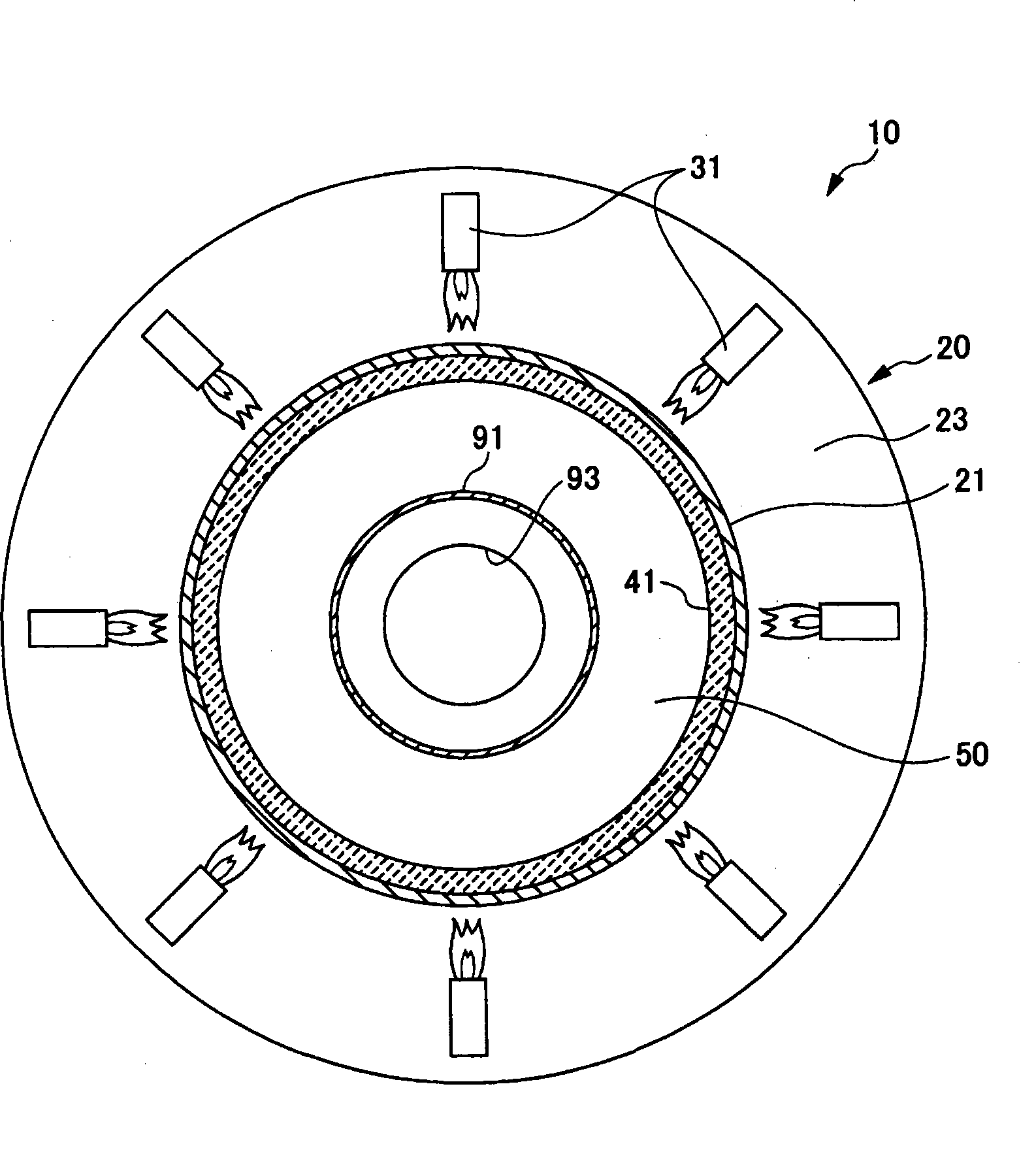
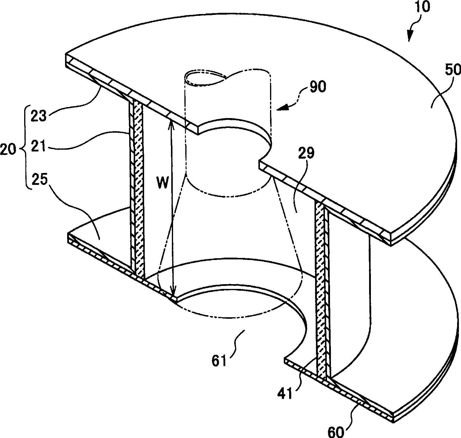
[0065] figure 1 It is a schematic configuration diagram of the heating device 10 in the first embodiment of the present invention. in addition, figure 2 yes figure 1 A sectional view on the line II-II of image 3 yes figure 1 partial perspective view.

[0066] The heating device 10 includes a frame body 20 , a heating unit 30 as a heati...


PUM


Abstract

The present invention aims to provide a heating apparatus that can sufficiently suppress the occurrence of striae and the deterioration of optical properties, and that can reduce the maintenance burden. A heating apparatus 10 that is used for heating a flow path 90 for flowing out the molten glass includes an inner wall 21 which forms an entry hole 29 that a tip 91 of the flow path 90 can enter, heating portions 30 for heating the inner wall 21, and a high radiation portion 40 that is made of a high emissivity material. The high radiation portion 40 is arranged so as to face the tip 91 of the flow path 90 as well as a lower part thereof with a space therebetween when the heating apparatus 10 is used.

Description

technical field [0001] The present invention relates to a heating device, a glass manufacturing device, and a glass manufacturing method for heating a channel through which molten glass flows out. Background technique [0002] A general molten glass supply device includes a holding container for storing molten glass, and a flow path is provided in the holding container. As a result, the molten glass in the holding container flows out from the flow path to the outside. [0003] Here, when the temperature of the flow path is low, the molten glass located near the inner wall of the flow path is heavily cooled, while the molten glass located in the center away from the inner wall is slightly cooled. Therefore, since the temperature distribution in the molten glass flowing out from the flow path becomes non-uniform, streaks are caused. In addition, the glass crystallizes, which also leads to a decrease in the optical properties of the manufactured glass product. [0004] There...

Claims


Application Information

Patent Timeline
Patent Type & Authority Applications(China)
IPC IPC(8): C03B7/06C03B11/08
CPCC03B7/096C03B5/26C03B7/12
Inventor 坂井亮介
Owner OHARA
Learn More