
Image splicing method and apparatus

An image stitching and image technology, applied in the field of image processing, can solve the problems of inability to display, limit the flexibility of monitoring system use, increase the workload of staff, etc., and achieve the effect of ensuring intuitiveness, improving use flexibility, and reducing workload.

Inactive Publication Date: 2009-08-05
VIMICRO CORP
View PDF3 Cites 30 Cited by
  • Summary
  • Abstract
  • Description
  • Claims
  • Application Information

AI Technical Summary

Problems solved by technology

In this way, when a target moves from one monitoring area to another (such as at a corner), the situation reflected on the TV screen wall is not a very intuitive process. Familiarity can quickly reflect the moving process and location of the target. In the current monitoring system, the video information uploaded by the cameras monitoring the same scene from different angles cannot be intuitively displayed on the TV screen wall, which increases the The workload of the staff, the flexibility of use of the monitoring system itself is also limited

Method used


Image

  • Image splicing method and apparatus
  • Image splicing method and apparatus
  • Image splicing method and apparatus

Examples


Embodiment Construction

[0034] In order to make the object, technical solution and advantages of the present invention clearer, the present invention will be further described in detail below with reference to the accompanying drawings and examples.

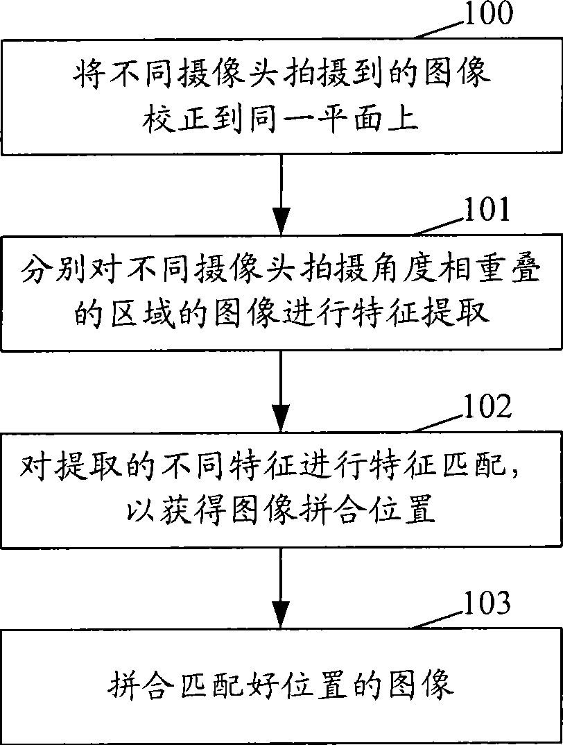
[0035] figure 1 It is a flow chart of the method for realizing image mosaic in the present invention, such as figure 1 shown, including:

[0036] Step 100: Correct the images captured by different cameras to the same plane.

[0037] Since the shooting angles of the cameras installed in different positions are different, firstly, the camera needs to be calibrated, that is, the shooting angle and the height of the camera need to be measured.

[0038] In order to reduce the difficulty, two cameras at different positions that can capture the same monitoring scene are taken as an example for description. The two cameras can be installed at the same height; based on the section at the center of the monitoring scene, the two cameras are rotated at the same ...


PUM


Abstract

The invention discloses an image spelling method and a device thereof. Image shoot by various camera is corrected to a same plane for extracting characteristic to region with overlap shooting angle by various camera, processing characteristic matching to extracted various characteristic for obtaining image spelling position and spelling image with matched position. The method can link camera for monitoring same scene with various angle in display image information directly, let missionary seeing monitor effect directly. The method and the device can ensure visibility for monitoring video, increase using flexibility of the monitoring system and reduce working load of the missionary.

Description

technical field [0001] The invention relates to image processing technology, in particular to an image splicing method and device. Background technique [0002] The video surveillance system is playing an increasingly important role. For some emergencies, the video recorded by the video surveillance system can be analyzed to find the appropriate basis to determine the responsibility of the incident and the personnel involved, so as to achieve the purpose of monitoring. [0003] In the existing video monitoring system, each camera transmits the video information captured by its own monitoring area to the monitoring room to realize video information sharing and display the status of each monitoring area on the TV screen wall. [0004] Currently, there is no relationship between the video images uploaded by each camera, they are independent of each other. In this way, when a target moves from one monitoring area to another (such as at a corner), the situation reflected on the ...

Claims


Application Information

Patent Timeline
Patent Type & Authority Applications(China)
IPC IPC(8): G06T5/00G06T7/00H04N7/18
Inventor 谌安军
Owner VIMICRO CORP
Learn More