Solenoid and connector assembly

A connector assembly, solenoid technology, applied in transformer/coil connectors, multi-conductor connectors, connections, etc., can solve problems such as failure of related components or controllers, failure of motors or solenoids, etc.

Inactive Publication Date: 2009-08-05
GENERAL MOTORS COMPANY
View PDF0 Cites 9 Cited by
  • Summary
  • Abstract
  • Description
  • Claims
  • Application Information

AI Technical Summary

Problems solved by technology

In addition, failure of a motor or solenoid due to a short circuit to ground may have subsequent failure of associated components or controllers

Method used


Image

  • Solenoid and connector assembly
  • Solenoid and connector assembly
  • Solenoid and connector assembly

Examples


Embodiment Construction

[0022] The following description is merely exemplary in nature and is not intended to limit the disclosure, application or use.

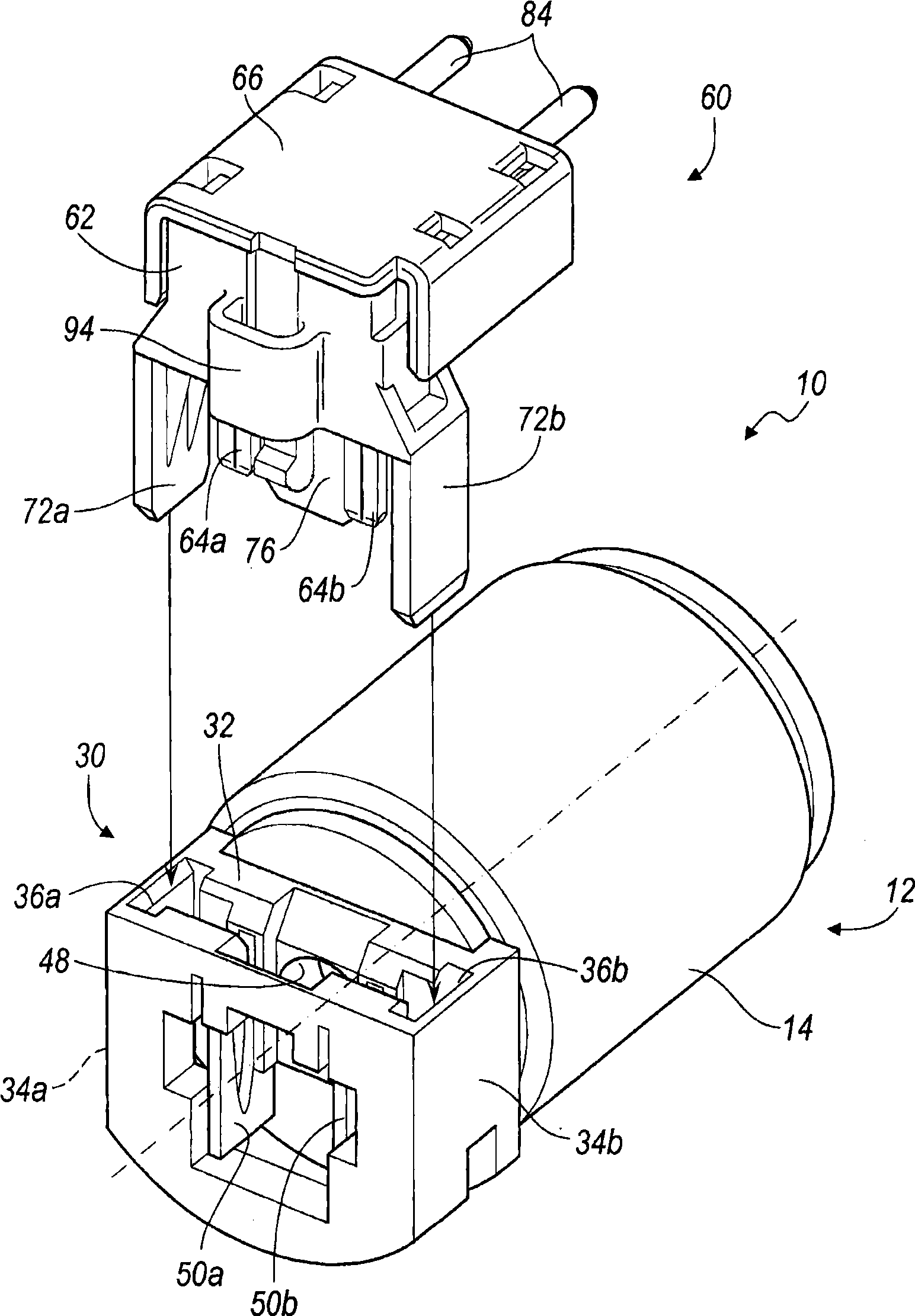
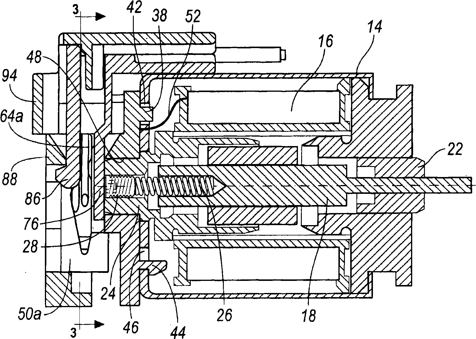
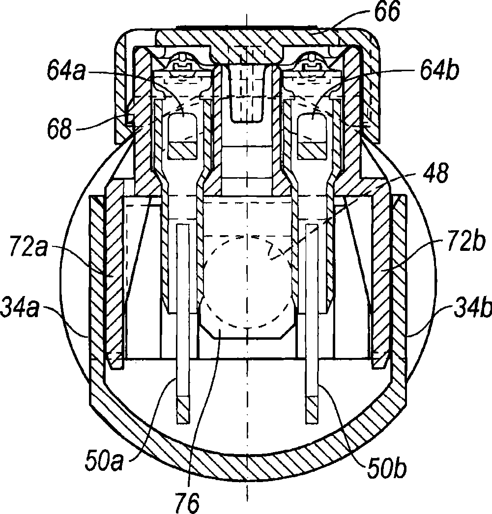
[0023] now refer to figure 1 and figure 2 , depicts a first embodiment of a solenoid and electrical connector assembly and is shown generally at 10 . The solenoid and electrical connector assembly first embodiment 10 includes a solenoid 12 having a generally cylindrical body or housing 14, preferably made of metal, such as steel, aluminum or Alloys of these or other metals. The cylindrical housing 14 positions, supports and protects the electrical coil 16 . The electrical coil 16 generally surrounds a bidirectionally translatable armature or plunger 18 . This plunger 18 cooperates with a first axial guide or bearing 22 and a second axial guide, pole piece or stop 24, said first axial guide or bearing 22 and a second axial guide, pole The plates or stops 24 together define an axis of movement or translation of the plunger 18 . A portion of the...


PUM


Abstract

The present invention provides a solenoid and electrical connector assembly which includes a solenoid body having a pair of electrical terminals disposed on opposite sides of a plunger component and a connector having two corresponding electrical terminals and a non-conductive blade or tongue disposed therebetween. When assembled, the tongue of the connector seats between the terminals on the solenoid body and inhibits corrosion and ingress of foreign matter in the region between the terminals of the solenoid.

Description

technical field [0001] The present invention relates to electrical connectors and electrical devices, and more particularly to an assembly of an electrical device (such as a motor or solenoid) and an electrical connector with improved reliability. Background technique [0002] The statements in this section merely provide background information related to the present invention which may or may not constitute prior art. [0003] Compact electrical devices, such as motors and solenoids, are often housed in a cylindrical housing that roughly corresponds to the moving parts of the device: in the case of a motor, a rotor surrounded by a cylindrical stator or in the case of a screw. In the case of conduit, a plunger surrounded by a cylindrical coil. Such a cylindrical housing is an efficient package for such a device, as the housing overall requires the least amount of material and results in a package of minimal size. [0004] Since one end of a typical motor or solenoid includ...

Claims


Application Information

Patent Timeline
Patent Type & Authority Applications(China)
IPC IPC(8): H01R24/06H01R13/629H01R31/06H01R13/02H02K5/22
CPCH01R2201/22H01R4/183H01R13/6272H01R4/4863H01R11/05
Inventor R·L·申克J·吉尔伯格T·H·威尔逊
Owner GENERAL MOTORS COMPANY
Why Eureka
Try Eureka