Mutual interference preventing control method for multi-mode terminal and mutual interference preventing multi-mode terminal

A technology of a multi-mode terminal and a control method, applied in the field of mobile communication, can solve the problems of inability to completely eliminate interference, occupy more space, and lengthen the distance, and achieve the effects of reliable effect, simple realization and obvious effect.

Inactive Publication Date: 2009-08-05
QINGDAO HISENSE MOBILE COMM TECH CO LTD
View PDF0 Cites 15 Cited by
  • Summary
  • Abstract
  • Description
  • Claims
  • Application Information

AI Technical Summary

Problems solved by technology

At the same time, in the control of wireless indicators, the distance between the CDMA antenna and the GSM antenna can only be extended as far as possible. The current solution is to place the CDMA antenna and the GSM antenna at the two ends of the mobile phone, so that two brackets are required. Therefore, it needs to take up more space. More importantly, even if two antennas are placed at both ends of the mobile phone, the interference cannot be completely eliminated. There are still relatively large interferences in several channels with the same frequency for CDMA reception and GSM transmission.

Method used


Image

  • Mutual interference preventing control method for multi-mode terminal and mutual interference preventing multi-mode terminal
  • Mutual interference preventing control method for multi-mode terminal and mutual interference preventing multi-mode terminal
  • Mutual interference preventing control method for multi-mode terminal and mutual interference preventing multi-mode terminal

Examples


Embodiment Construction

[0022] The present invention will be described in detail below in conjunction with the accompanying drawings.

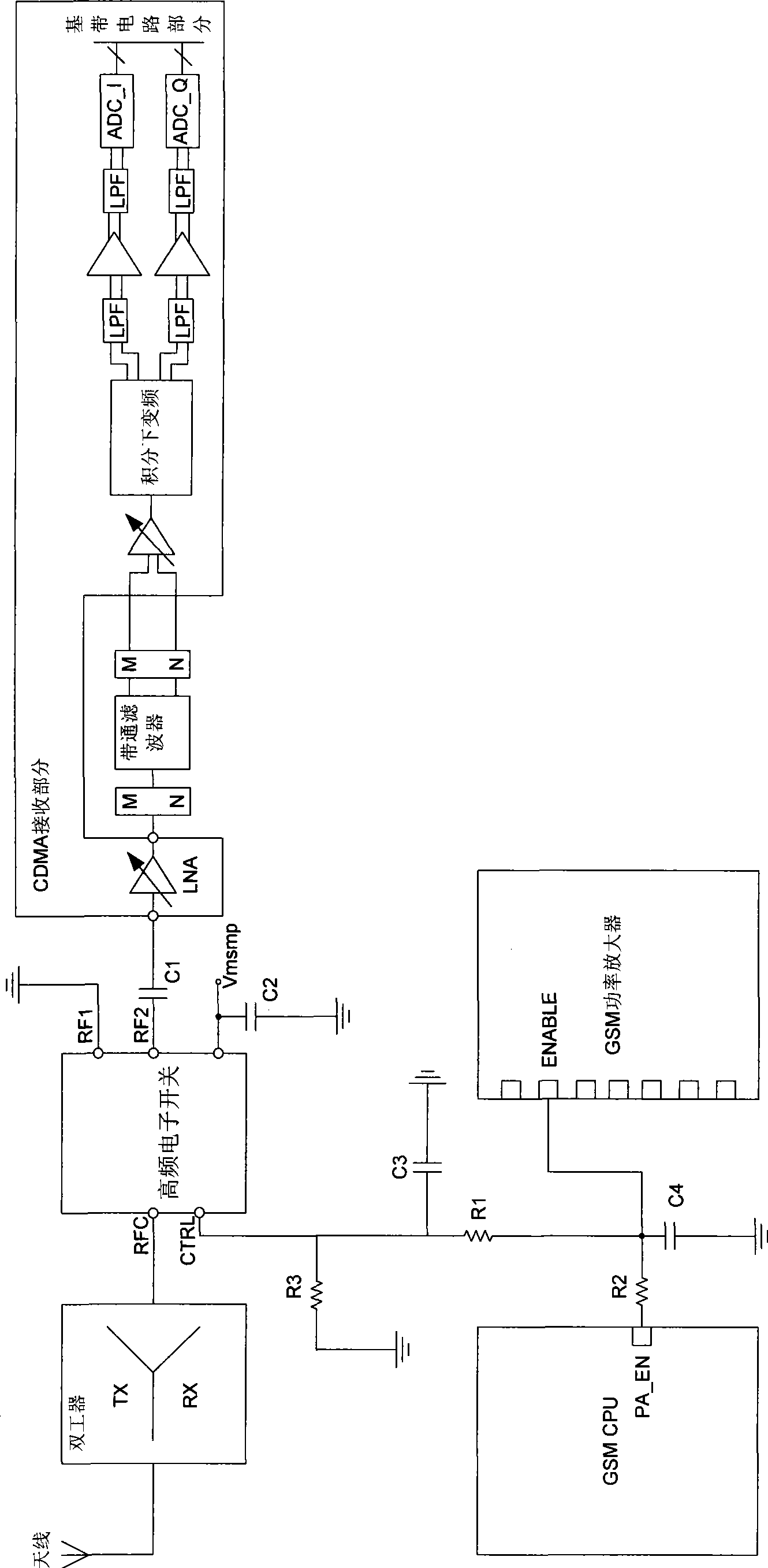
[0023] refer to figure 1 , is a schematic diagram of a partial structure of an embodiment of an anti-interference multimode terminal according to the present invention. As shown in the figure, what is shown in this embodiment is a CDMA and GSM dual-mode dual-standby mobile terminal.

[0024] For the GSM part, the figure has only shown the GSM CPU and the GSM power amplifier directly related to the present invention; for the CDMA part, it has only shown its radio frequency part (that is, the CDMA receiving part shown in the figure), and for the Its baseband circuit part is not shown in the figure.

[0025] Because the transmitting frequency band of GSM is between 880MHz to 915MHz, and the receiving frequency band of CDMA is between 869MHz to 894MHz, there is an overlapping area between the two, so with these two situations, it is explained, for illustrating the tech...


PUM


Abstract

The invention discloses a control method for preventing mutual interference of multimode terminals. The method comprises the following steps: a first-mode state based on time division multiple access is obtained, if in emission state, a second-mode receiving path is disconnected; and then when the first mode is separated from the emission state, the second-mode receiving path is restored. In the invention, as the first mode based on time division multiple access is in emission state, the second-mode receiving path is disconnected; besides, as a one-time emission period of the first mode based on time division multiple access is a time slot, the time is short and the second mode has an own mechanism for correcting errors, thus having no influence to the demodulation of the second mode under the premise of solving the mutual interference problem, and effectively solving the problem of multimode mutual interference. The invention provides a multimode terminal for preventing mutual interference.

Description

technical field [0001] The invention relates to the field of mobile communication, in particular to a multi-mode terminal mutual interference prevention control method and a mutual interference prevention multi-mode terminal. Background technique [0002] When the CDMA and GSM dual-mode dual-standby mobile phone is working, because the CDMA and GSM are on standby at the same time, there will be a problem of mutual interference between the CDMA mode and the GSM mode when working at the same time. Since there is an overlapping area between the GSM transmit frequency band (880MHz-915MHz) and the CDMA receive frequency band (869MHz-894MHz), when CDMA and GSM work at the same time, the GSM transmit signal will be received by the CDMA antenna and enter the CDMA demodulation , thus causing interference to the CDMA receiving frequency band. [0003] For the current CDMA and GSM dual-mode dual-standby mobile phones, in order to eliminate mutual interference, the two modes of CDMA an...

Claims


Application Information

Patent Timeline
Patent Type & Authority Applications(China)
IPC IPC(8): H04B1/52H04B1/44H04W88/06H04B1/525
Inventor 李勇秦明鑫高一伦
Owner QINGDAO HISENSE MOBILE COMM TECH CO LTD
Why Eureka
Try Eureka