End face grinding apparatus, and method of grinding end face, for glass substrate

A glass substrate, end face grinding technology, applied in grinding/polishing safety devices, machine tools suitable for grinding workpiece planes, grinding/polishing equipment, etc. marks, etc.

Active Publication Date: 2009-08-05
NIPPON ELECTRIC GLASS CO LTD
View PDF7 Cites 15 Cited by
  • Summary
  • Abstract
  • Description
  • Claims
  • Application Information

AI Technical Summary

Problems solved by technology

That is, the purpose of either of the above-mentioned Patent Documents 3 and 4 is to prevent the contamination of the surface of the glass substrate due to cutting chips, and there is no consideration for the occurrence of scratches on the surface of the glass substrate due to the cutting chips.
Described in detail, the method disclosed in the above-mentioned Patent Document 3 is to remove the cutting chips adhering to the surface of the glass substrate by a water flow and an air flow formed along the surface of the glass substrate on the downstream side of the grinding part of the glass substrate in the conveying direction of the glass substrate. It is discharged to the outside of the end of the glass substrate. Therefore, when the chips contained in the grinding fluid scattered from the grinding part of the glass substrate adhere to the surface of the glass substrate while flowing strongly along the surface of the glass substrate, the adhered Chips may have scratched the surface of the glass substrate at the stage of being discharged by water flow and air flow
In addition, as disclosed in this document, even if an air flow is separately formed toward the grinding part of the glass substrate, it is difficult to reliably block the flow of chips contained in the grinding fluid along the glass substrate, and there is still a gap between the glass substrate due to the chips. Possibility of surface scratches
[0016] In addition, in the method disclosed in the above-mentioned Patent Document 4, since the water flow formed by the water curtain along the surface of the glass substrate is brought into contact with the cutting water jetted substantially perpendicularly to the surface of the glass substrate, there is cutting water flowing along the surface of the glass substrate. Possibility of flow while accelerating in the direction of the surface of the glass substrate
In addition, when the above-mentioned situation occurs, chips contained in the cutting water rub against the surface of the glass substrate while strongly contacting, and there is a possibility that scratches may be generated on the surface of the glass substrate.

Method used


Image

  • End face grinding apparatus, and method of grinding end face, for glass substrate
  • End face grinding apparatus, and method of grinding end face, for glass substrate
  • End face grinding apparatus, and method of grinding end face, for glass substrate

Examples


Embodiment Construction

[0039] Hereinafter, embodiments of the present invention will be described with reference to the drawings.

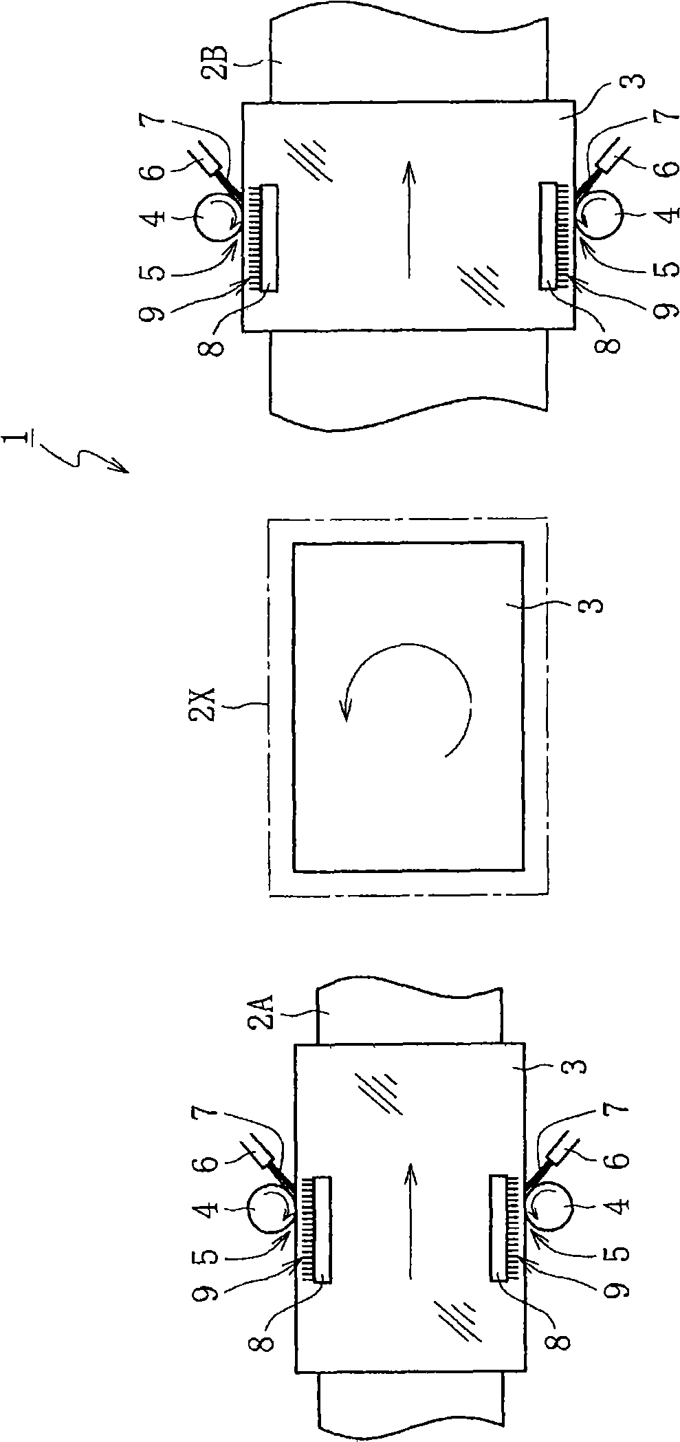
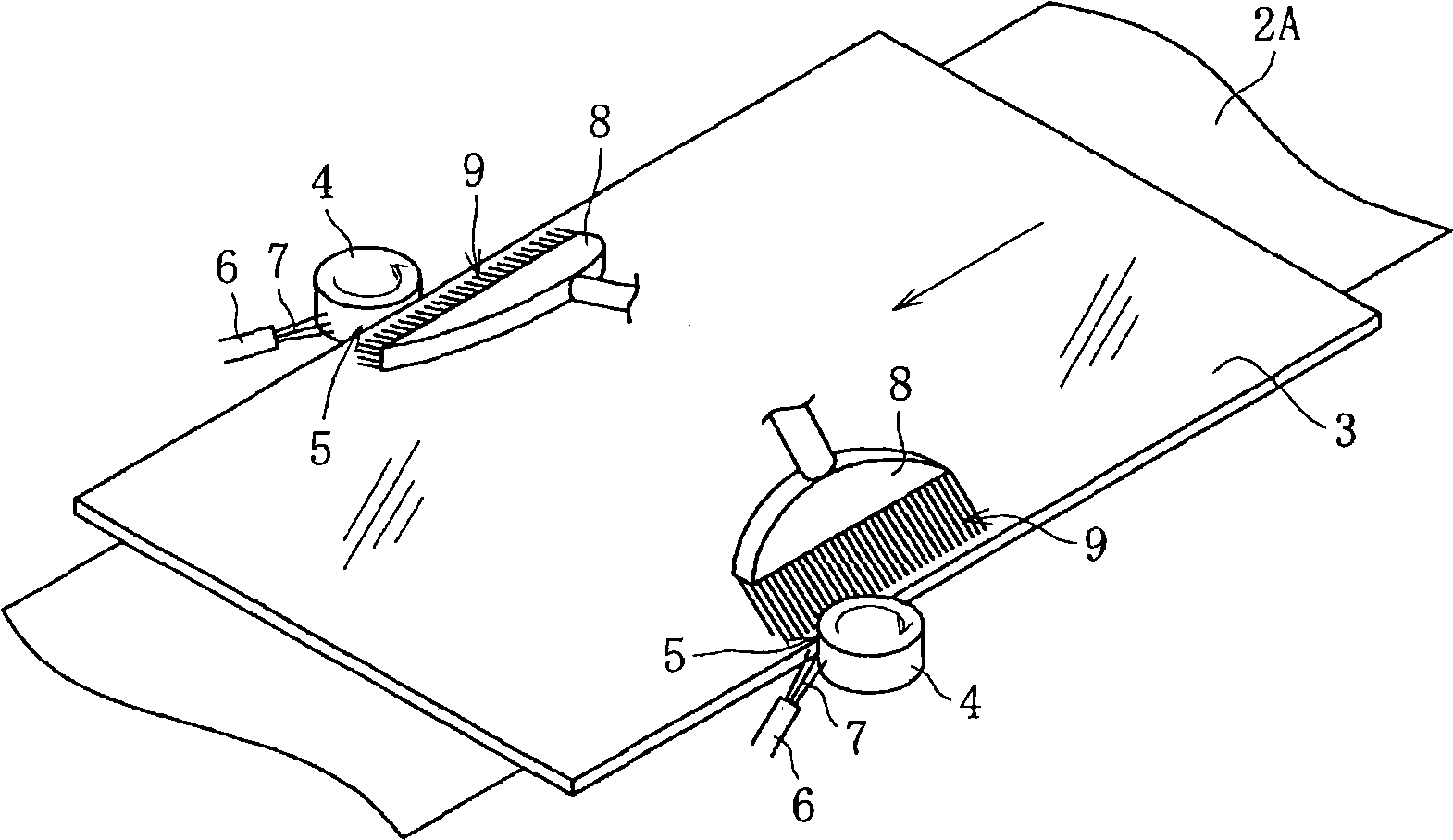
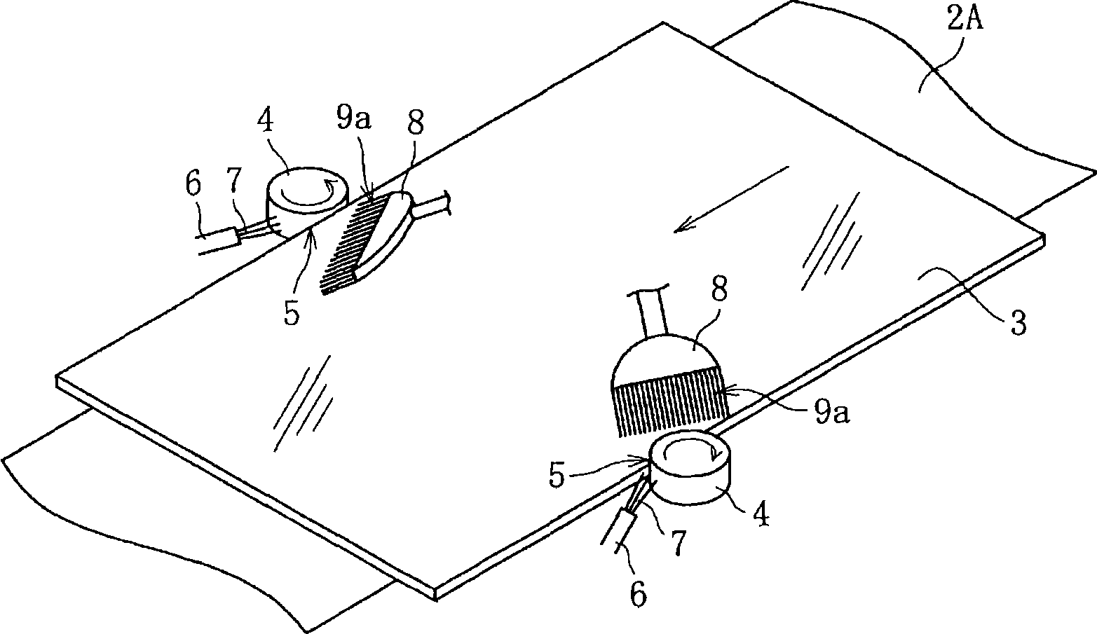
[0040] First, based on figure 1 The schematic plan view shown demonstrates the whole structure of the end surface grinding apparatus of the glass substrate which concerns on one Embodiment of this invention. In addition, in this embodiment, a glass substrate is a glass substrate for liquid crystal displays.

[0041] As shown in the figure, in this end surface grinding apparatus 1, the glass substrate 3 is transported in a horizontal posture in the horizontal direction (rightward direction in the figure) by the upstream transport mechanism 2A, and the rotation adjacent to the downstream side The mechanism 2X horizontally rotates the glass substrate 3 by 90°, and further conveys the horizontally rotated glass substrate 3 in the same direction by the downstream conveyance mechanism 2B adjacent to the downstream side. In addition, since the upstream conveying mechanism 2A...


PUM


Abstract

End face grinding apparatus (1) for glass substrate including grindstone (4) for grinding an end face of glass substrate (3) by making relative movement to the glass substrate (3) and including grinding fluid supply means (6) for feeding grinding fluid (7) to an area surrounding a grind location of the glass substrate (3), wherein there is disposed water spouting means (8) for forming water curtain (9) adapted to block the flow along the surface of the glass substrate (3) of any cut dust contained in the grinding fluid (7) scattered in the grinding of the end face of the glass substrate (3) by the grindstone (4).

Description

technical field [0001] The present invention relates to an end surface grinding device for a glass substrate and an end surface grinding method thereof. Specifically, it relates to a technical improvement for grinding an end surface of a glass substrate while supplying a grinding liquid to a grinding part of the glass substrate. Background technique [0002] As is well known, in the production of glass substrates for various image display devices such as liquid crystal displays, plasma displays, electroluminescent displays, and field emission displays, a method of producing a plurality of glass substrates from one rough-worked plate glass is used. In addition, as a result of the present situation, rough-processed plate glass produced by glass manufacturers is gradually increasing in size. [0003] In the final stage of the manufacturing process of these rough-processed plate glasses, after cutting the glass substrate into a rectangular shape and a predetermined size, the cut...

Claims


Application Information

Patent Timeline
Patent Type & Authority Applications(China)
IPC IPC(8): B24B9/10B24B7/24B24B55/06
CPCB24B55/02B24B9/10
Inventor 西村直树田中重刚
Owner NIPPON ELECTRIC GLASS CO LTD
Why Eureka
Try Eureka