Discharge lamp, in particular low pressure discharge lamp

A technology for low-pressure discharge lamps and discharge lamps, applied to low-pressure discharge lamps, discharge lamps, gas discharge lamps, etc., which can solve the problems of degraded photoelectric value, high working amalgam temperature, and high cost, and achieve the effect of improving regulation

Inactive Publication Date: 2009-08-05
OSRAM GMBH
View PDF1 Cites 0 Cited by
  • Summary
  • Abstract
  • Description
  • Claims
  • Application Information

AI Technical Summary

Problems solved by technology

In the known compact fluorescent lamps, the problem arises that the temperature of the working amalgam is too high, thereby deteriorating the photoelectric value
However this is usually very expensive and only achieves conditional improvements

Method used


Image

  • Discharge lamp, in particular low pressure discharge lamp
  • Discharge lamp, in particular low pressure discharge lamp
  • Discharge lamp, in particular low pressure discharge lamp

Examples


Embodiment Construction

[0027] In the figures, identical or functionally identical elements are provided with the same reference symbols.

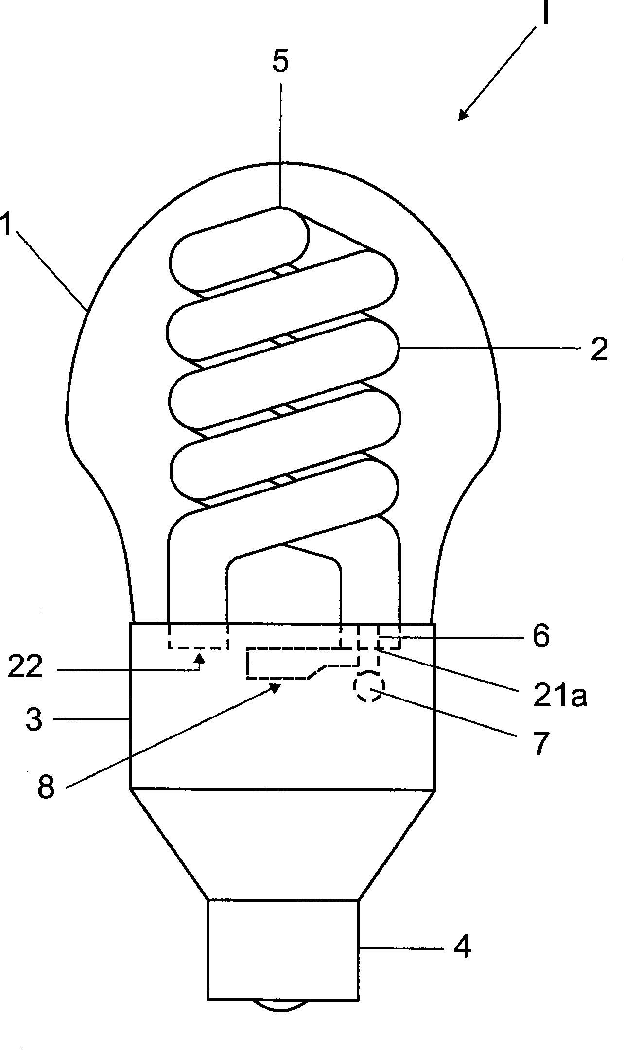
[0028] exist figure 1 shows a discharge lamp 1 constructed as a compact fluorescent lamp with an outer bulb 1 . The envelope bulb 1 surrounds a helically wound discharge vessel 2 . The tubular and helically wound discharge vessel 2 is connected to an electronic ballast, shown only by its housing 3 . The housing bulb 1 is also fastened to the housing 3 via locking elements.

[0029] On the side facing away from the enveloped bulb 1 , the housing 3 of the ballast is terminated by a standardized base 4 . In this embodiment, the discharge vessel 2 consists of two coiled discharge tubes which meet each other in a region 5 .

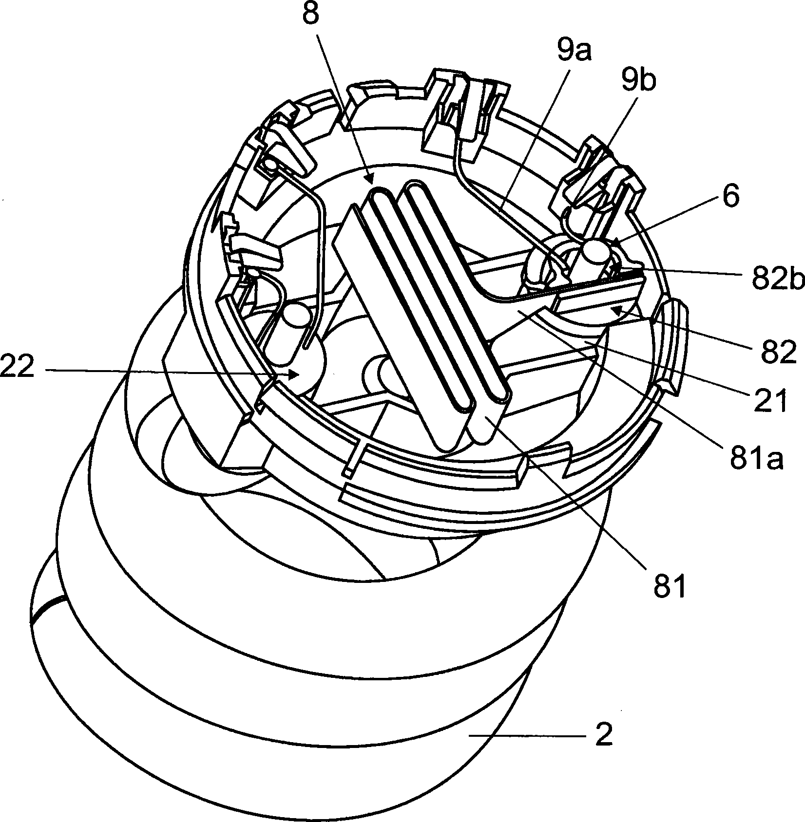
[0030] The two ends 21 and 22 of the discharge vessel 2 are arranged substantially opposite each other and with the same orientation in the direction of the housing 3 . as from figure 1 As can be seen in the view of , these ends 21 and 22 e...


PUM


Abstract

The invention relates to a discharge lamp, in particular a low pressure discharge lamp, with a discharge vessel (2) and a tubular piece (6) that is attached to the discharge vessel (2), with an Hg source (7) arranged in the tubular piece, and a cooling device (8) designed on the tubular piece (6) for dissipating the heat of at least the tubular piece that heats up during the operation of the discharge lamp (I).

Description

technical field [0001] The invention relates to a discharge lamp, in particular a low-pressure discharge lamp, which has a discharge vessel and a tube arranged on the discharge vessel, the Hg source being arranged in the tube. Background technique [0002] Gas discharge lamps have been widely used for a long time, especially in the form of compact fluorescent lamps. It is customary here for the gas discharge lamp to have an integrated electronic ballast or for the gas discharge lamp to be connected to a separate electronic ballast. Conventional discharge lamps have a generally liquid mercury source (Hg source) from which a suitable amount of mercury evaporates during operation, wherein the Hg vapor is excited by electron collisions and leads to the generation of UV radiation. Basically, the term Hg source here in principle encompasses two functions, namely on the one hand the function of the Hg donor. A mercury source is a material or body that contains mercury. In additi...

Claims


Application Information

Patent Timeline
Patent Type & Authority Applications(China)
IPC IPC(8): H01J61/52H01J61/70H01J61/28
CPCH01J61/523H01J61/70H01J61/327H01J61/28
Inventor 霍尔格·海因
Owner OSRAM GMBH
Why Eureka
Try Eureka