
Fixation hook for correcting malformation of vertebral column

A spinal deformity and fixation hook technology, applied in the field of fixation hooks, can solve the problems of inconvenient operation by doctors and achieve the effect of convenient connection

Inactive Publication Date: 2009-08-12
于凤章
View PDF0 Cites 5 Cited by
  • Summary
  • Abstract
  • Description
  • Claims
  • Application Information

AI Technical Summary

Problems solved by technology

In addition, the position where the upper support hook supports the ribs is located at the position of the strut, which is not convenient for the doctor to operate during the operation

Method used


Image

  • Fixation hook for correcting malformation of vertebral column
  • Fixation hook for correcting malformation of vertebral column

Examples


Embodiment Construction

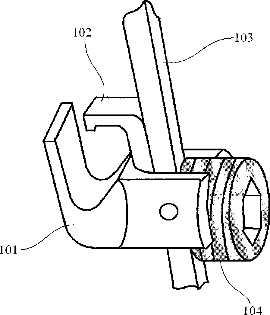
[0020] Such as figure 1 As shown, according to the fixation hook used to correct spinal deformity in the prior art, the supporting hook 101 generally supports the ribs, and a protective hook 102 is provided to prevent the supported ribs from being separated from the supporting hook 101 as the child moves or increases in height. . The supporting hook 101 can be slid to a proper height on the supporting rod 103, and then locked on the supporting rod 103 by the locking screw 104.

[0021] The center line of the support hook 101 and the center line of the support rod 103 coincide with each other. In this way, the position of the support rib of the support hook 101 can only be located at the position of the support rod 103. Therefore, the thickness of the hook body is relatively thick and the degree of freedom to choose the support point is small. . In addition, the position where the supporting hook 101 supports the ribs is located at the position of the strut 103, which makes it not...


PUM


Abstract

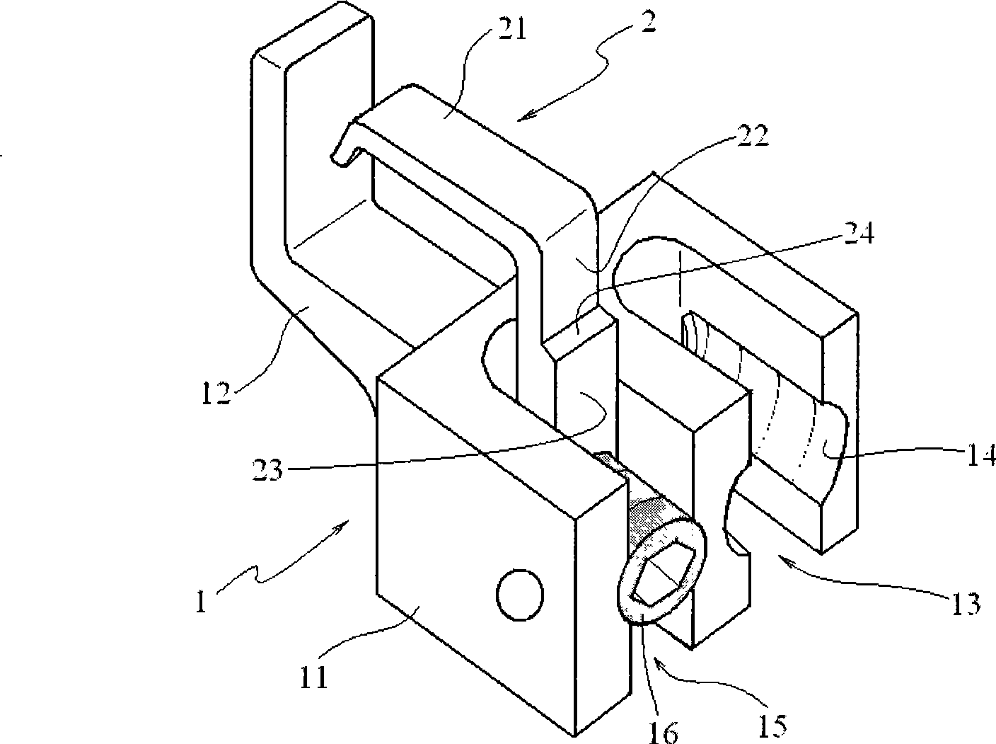
A fixation hook used for correcting spinal deformity comprises a fixation hook body and a protective hook. The fixation hook is characterized in that the fixation hook body comprises a locking groove connected with a brace rod, a locking groove connected with the protective hook and a hook head; wherein, the locking groove connected with the brace rod is positioned on one side of and parallel to the locking groove connected with the protective hook; thus, the locking groove connected with the brace rod and the locking groove connected with the protective hook are mutually separated in parallel and can not increase the thickness of the hook body; the position on which a rib is supported by a support hook is not changed, which can be far away from the brace rod and a spine so as to bring the supporting function into full play. In particular, the protective hook is provided with a clamping platform at the kink of the hook, the neck of the hook is long and the hook head has at least two types of length, thereby being convenient for the doctors to use the apparatus during the operation.

Description

Technical field [0001] The invention relates to a fixing hook used for correcting spinal deformities, in particular to a fixing hook of a rib corrector for congenital spinal deformity at a young age. Background technique [0002] In the prior art, the support point above the built-in orthosis is moved to the upper rib, and the lower support point can be on the lower rib, spine, or ilium. By spreading the ribs, on the one hand, the supporting force can be transmitted to the spine to achieve the purpose of correcting spinal deformities. On the other hand, the spreading of the ribs enlarges the chest cavity and corrects the development of the heart and lung organs of children who are good for growth and development. If the lower support point is on the lumbar spine or ilium, it is also beneficial to the development of abdominal organs. Research and clinical practice in recent years have shown that the spontaneous fusion of the vertebral body is less likely to occur when the upper su...

Claims


Application Information

Patent Timeline
IPC IPC(8): A61B17/70
CPCA61B17/7047
Inventor 于凤章
Owner 于凤章
Learn More