
Hand back plate special for two-stage type operating table with joint

An operating bed, two-stage technology, applied in the direction of surgery, operating table, medical science, etc., can solve the problems affecting the accuracy of arterial pressure and oxygen saturation, the inability to observe the puncture and monitoring sites, and the injury of both doctors and patients. Achieve the effect of avoiding brachial plexus injury, eliminating brachial plexus injury, and convenient use

Active Publication Date: 2009-08-12
南京鼎世医疗器械有限公司
View PDF0 Cites 5 Cited by
  • Summary
  • Abstract
  • Description
  • Claims
  • Application Information

AI Technical Summary

Problems solved by technology

However, there are the following obvious defects in the operation of the thoracoabdominal region in this straight-type dorsal hand board:
[0003] 1. When the back of the hand is placed close to the patient's body or tilted toward the foot, although a spacious operating area is provided for the surgeon, it is convenient for the operation, but the intravenous infusion, radial artery puncture and oxygen saturation monitoring of most patients are all unreliable. Located on the forearm and hand, the anesthesiologist and the itinerant nurse cannot observe the puncture and monitoring site after being covered by the surgical drape. At the same time, the operation of the surgeon will interfere with the hand, affecting the accuracy of arterial pressure and oxygen saturation
[0004] 2. When the back of the hand is perpendicular to the body or tilted toward the head, the surgical operation and anesthesia monitoring will not be affected, but the brachial plexus may be damaged if the brachial plexus is overextended in the upper arm, especially in patients with long-term surgery. Nerve injury accidents often occur, causing great harm to both doctors and patients

Method used


Image

  • Hand back plate special for two-stage type operating table with joint

Examples


Embodiment Construction

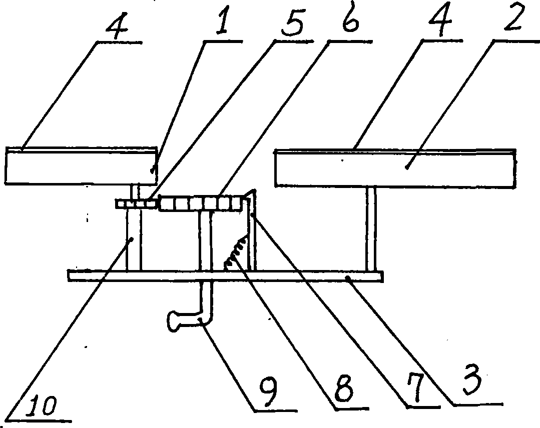
[0012] Such as figure 1 Shown:

[0013] The movable plate 1 and the fixed plate 2 are on the same plane and connected in a straight line, leaving a gap between the two so that the movable plate 1 can rotate on this plane; the movable plate 1 and the fixed plate 2 are provided with a layer Cushion 4; the support plate 3 is connected below the fixed plate 2, and the driving gear 6 is arranged on the support plate 3 (in the middle); The driving gear shaft 10 is connected to the support plate 3; the driving gear 6 meshes with the driven gear 5, and the driving gear 6 and the driven gear 5 are on a plane parallel to the plane formed by the movable plate 1 and the fixed plate 2 And below it; a buckle 7 is set on the outer periphery of the driving gear 6, the upper end of the buckle 7 is connected to the teeth of the driving gear 6, the lower end is connected to the support plate 3, and one end of the extension spring 8 is connected to the middle part of the buckle 7. The other end...


PUM


Abstract

The invention relates to a hand back plate special for a two-stage operating table with joints, comprising a portable plate and a fixing plate; the portable plate is fixedly connected with a driven gear which is connected with a driven gear shaft in a rotary way; the driven gear shaft is connected on a support plate; the fixing plate is connected with the support plate; a driving gear shaft is connected with the support plate in a rotary way; the driving gear is meshed with the driven gear; the plane on which the driving gear and the driven gear are positioned is parallel to the plane on which the fixing plate is positioned. The invention eliminates the defects of the hand back plate, including effects on observing the sites of puncture and monitoring, disturbance on operation, accuracy of arterial pressure and oxygen saturation, brachia plexus injury of patients and the like. By using the invention, upper limbs of the patients can be placed on the body positions which can naturally bend and relax and the brachial plexus is free from traction, thus providing a larger operation space for operating surgeons, facilitating observation of intravenous infusion and sites of puncture of arteria radialis and ensuring fingertip oxygen saturation and arterial pressure monitoring free from disturbance.

Description

technical field [0001] The invention relates to a medical auxiliary device, in particular to a special hand back board for an operating bed. Background technique [0002] Before the present invention, the back of the hand on the current operating bed is a complete straight plate, which can be fixed on the operating bed and rotate around the fixed place on the same plane as the operating bed to the patient’s head or foot to support the patient during surgery arm. However, there are the following obvious defects in the operation of the thoracoabdominal region in this straight-type dorsal hand board: [0003] 1. When the back of the hand is placed close to the patient's body or tilted toward the foot, although a spacious operating area is provided for the surgeon, which is convenient for operation, but most patients cannot perform intravenous infusion, radial artery puncture and oxygen saturation monitoring. Located on the forearm and hand, the anesthesiologist and the itiner...

Claims


Application Information

Patent Timeline
Patent Type & Authority Applications(China)
IPC IPC(8): A61G13/12
Inventor 蒋忠华薇符蓓蓓
Owner 南京鼎世医疗器械有限公司
Learn More