
Non-gaseous coating apparatus

An airless spraying, cylinder technology, applied in coating, spraying device, liquid spraying device and other directions, can solve the problems of cylinder leakage, short service life, large air consumption, etc., to increase the service life and reduce the loss of gas , Improve the effect of coating quality

Inactive Publication Date: 2009-08-12
袁铁柱
View PDF0 Cites 7 Cited by
  • Summary
  • Abstract
  • Description
  • Claims
  • Application Information

AI Technical Summary

Problems solved by technology

[0003] 1. There is an air inlet or outlet hole on the side wall of the cylinder, which is easy to break the sealing ring when assembling the piston, resulting in internal leakage of the cylinder, so that the piston in the cylinder cannot move up and down evenly;
[0004] 2. The gas distribution block and the cylinder are of an integrated structure. When one of the gas distribution blocks or the cylinder is broken, the gas distribution block and the cylinder need to be replaced together, which increases the repair cost and causes serious waste;
[0005] 3. The air intake route is unreasonable. The gas must pass through the lower cover of the cylinder and then enter the reversing chamber assembly and the gas distribution block assembly, and finally enter the cylinder, thus causing the gas to travel from the lower cover of the cylinder to the upper pilot valve body. The air intake route is long, so it is easy to be blocked. The air intake route from the lower cover of the cylinder to the lower pilot valve body is short. When working, the upper and lower pilot valve bodies cannot be opened on time, resulting in insufficient sensitivity of the equipment. When spraying, a pulse is generated to make it crash and affect its normal work;
[0006] 4. The design of the air distribution block assembly and the reversing chamber assembly is unreasonable, resulting in short service life and large air consumption.

Method used

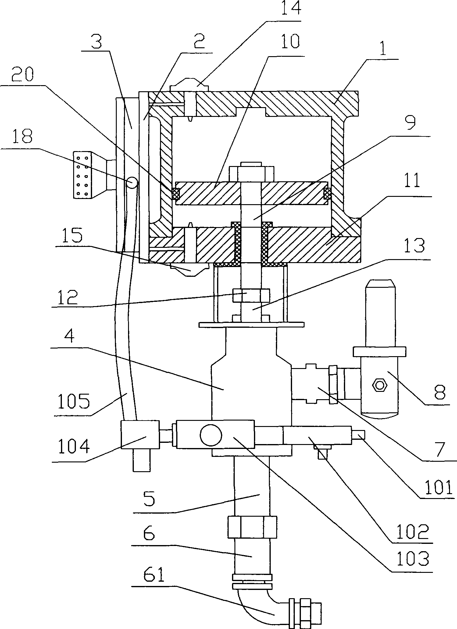

Image

  • Non-gaseous coating apparatus
  • Non-gaseous coating apparatus
  • Non-gaseous coating apparatus

Examples


Embodiment Construction

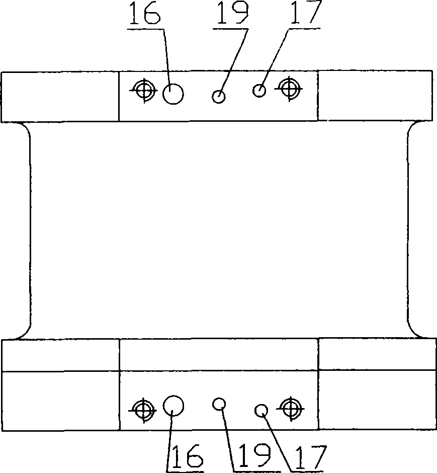
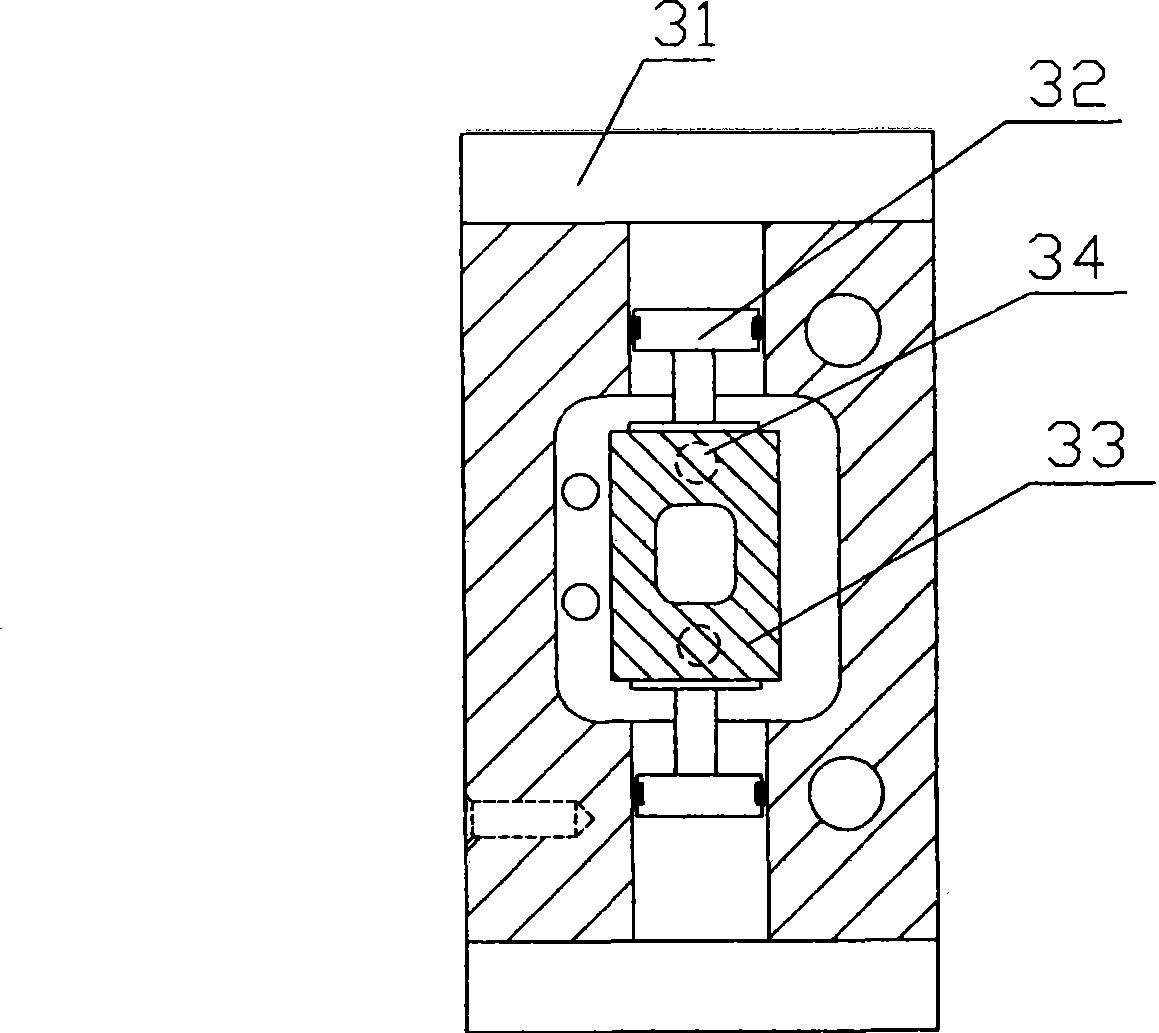
[0028] refer to figure 1 , figure 2 As shown, it is a preferred embodiment of the present invention, an airless spraying machine, including a cylinder 1, a chassis 11, an air distribution block assembly 2, a reversing chamber assembly 3, a pump seat assembly 4, a paint cylinder 5, Suction valve body 6, output joint 7, filter assembly 8, air intake joint 101, air intake tee 102, air intake filter element 103, lubricator 104 and air intake hose 105, wherein the cylinder 1 is closed and connected to the chassis 11 , the gas distribution block assembly 2 is closed and connected with the reversing chamber assembly 3, and an upper piston rod 9 and a piston 10 sleeved on the upper piston rod 9 are arranged in the cylinder 1, and one end of the upper piston rod 9 passes through the cylinder The lower cover 11 is connected with the lower piston rod 13 through the connecting head 12, and the pump seat assembly 4 is sleeved on the lower piston rod 13, and the paint cylinder 5 and the s...


PUM


Abstract

The invention discloses an airless spraying coater, comprising an air cylinder, a chassis, an air distributing block assembly, a reversing chamber assembly, a pump base assembly, a paint cylinder, a suction valve body, an output joint, a filter assembly, an air inlet joint, an air inlet tee, an air inlet filter core, an oil-mist device and an air inlet hose. The air cylinder is detachably connected with the air distributing block assembly. An air inlet channel, an air outlet channel and a reversing channel, which are capable of communicating the interior of the air cylinder with the air distributing block assembly, are respectively arranged at the top of the air cylinder and the chassis. An air inlet for allowing the entering of air is arranged on the side wall of the reversing chamber assembly. By using the structure, the invention has the advantages that the invention has a rational structural design and long service life, saves energy sources, does not easily go wrong, and can improve coating quality.

Description

technical field [0001] The invention discloses an airless spraying machine, which is mainly used for various oil-based paints, water-based paints and high-viscosity special paints, and belongs to the technical field of spraying equipment. Background technique [0002] At present, the airless spraying machines produced in China mainly include a cylinder and an air distribution block assembly with an integral structure with the cylinder. The block assembly is also connected with the reversing chamber assembly, a piston and a piston rod are arranged in the cylinder, an upper pilot valve body and a lower pilot valve body are arranged on the cylinder, and an air inlet hose is arranged on the lower cover of the cylinder to The air hose connects the lubricator, intake filter element, intake ball valve, intake tee and intake joint in turn. There is an oil cup on the lubricator, and a paint tank and pump seat in the middle of the lower cover of the cylinder. , the pump seat is conne...

Claims


Application Information

Patent Timeline
IPC IPC(8): B05B15/00B05B9/03B05C11/10B05C5/00
Inventor 袁蒋柱
Owner 袁铁柱
Learn More