Tool for mounting lower prestressing nut

An installation tool and prestressing technology, applied in the direction of manufacturing tools, metal processing, metal processing equipment, etc., can solve the problems of damaged tie rod threads or prestressed nut threads, complicated structure of auxiliary installation tools, and increased labor intensity of workers. Reduce installation time, large industrial utilization value, good installation effect

Active Publication Date: 2009-08-12
MCC CAPITAL ENGINEERING & RESEARCH
View PDF0 Cites 2 Cited by
  • Summary
  • Abstract
  • Description
  • Claims
  • Application Information

AI Technical Summary

Problems solved by technology

However, the traditional method of installation is very easy to damage the thread of the tie rod or the thread of the prestressed nut when the lifting nut is inserted into the tie rod
With the increase of the tonnage of the forging machine, the weight of the prestressed nut also increases, and limited by the narrow installation space, the labor intensity of the workers increases, or the auxiliary installation tools are complex in structure and difficult to operate

Method used


Image

  • Tool for mounting lower prestressing nut
  • Tool for mounting lower prestressing nut
  • Tool for mounting lower prestressing nut

Examples


Embodiment approach 1

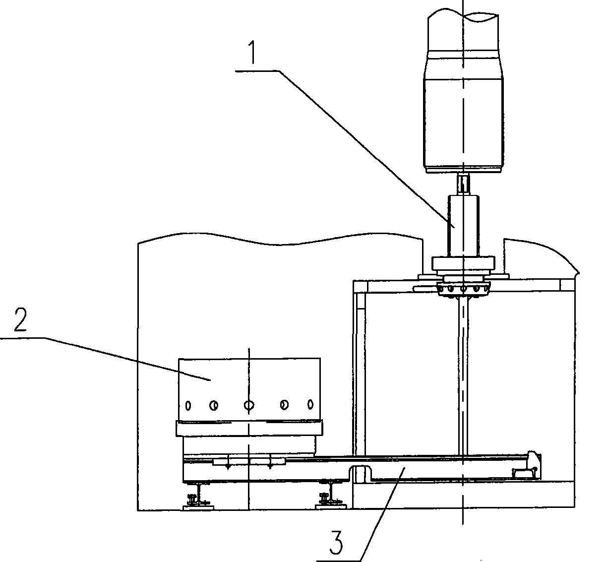
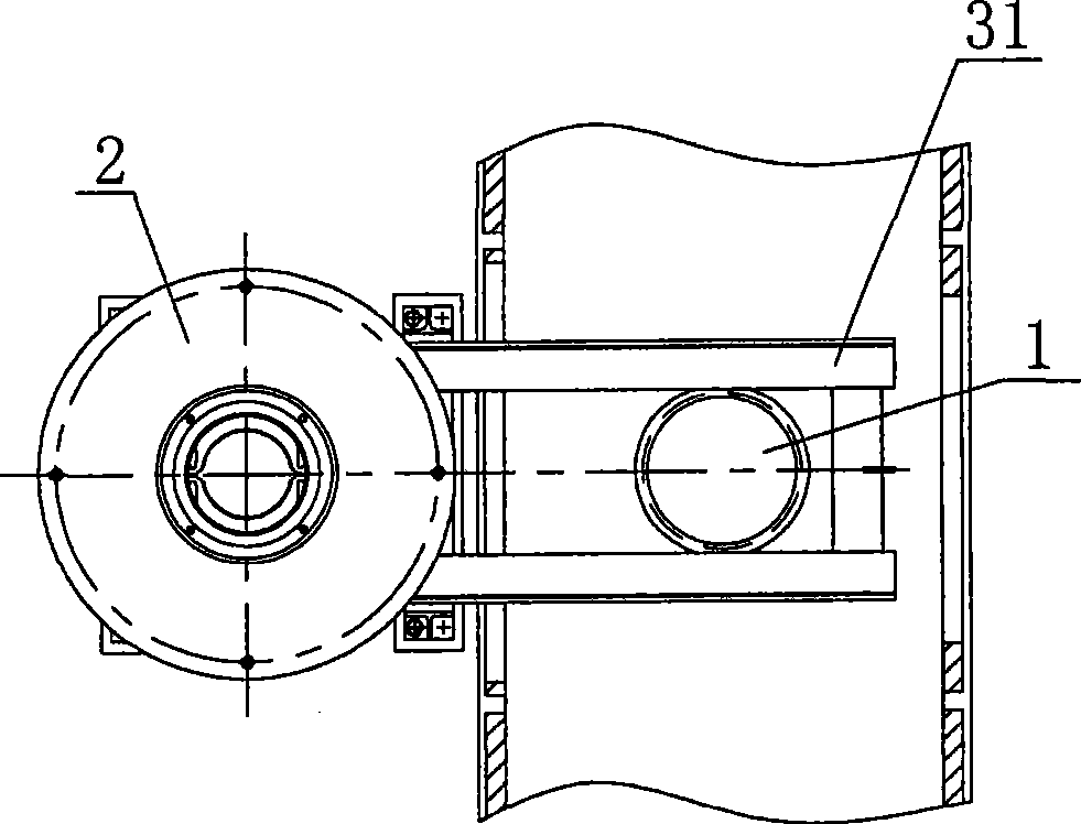
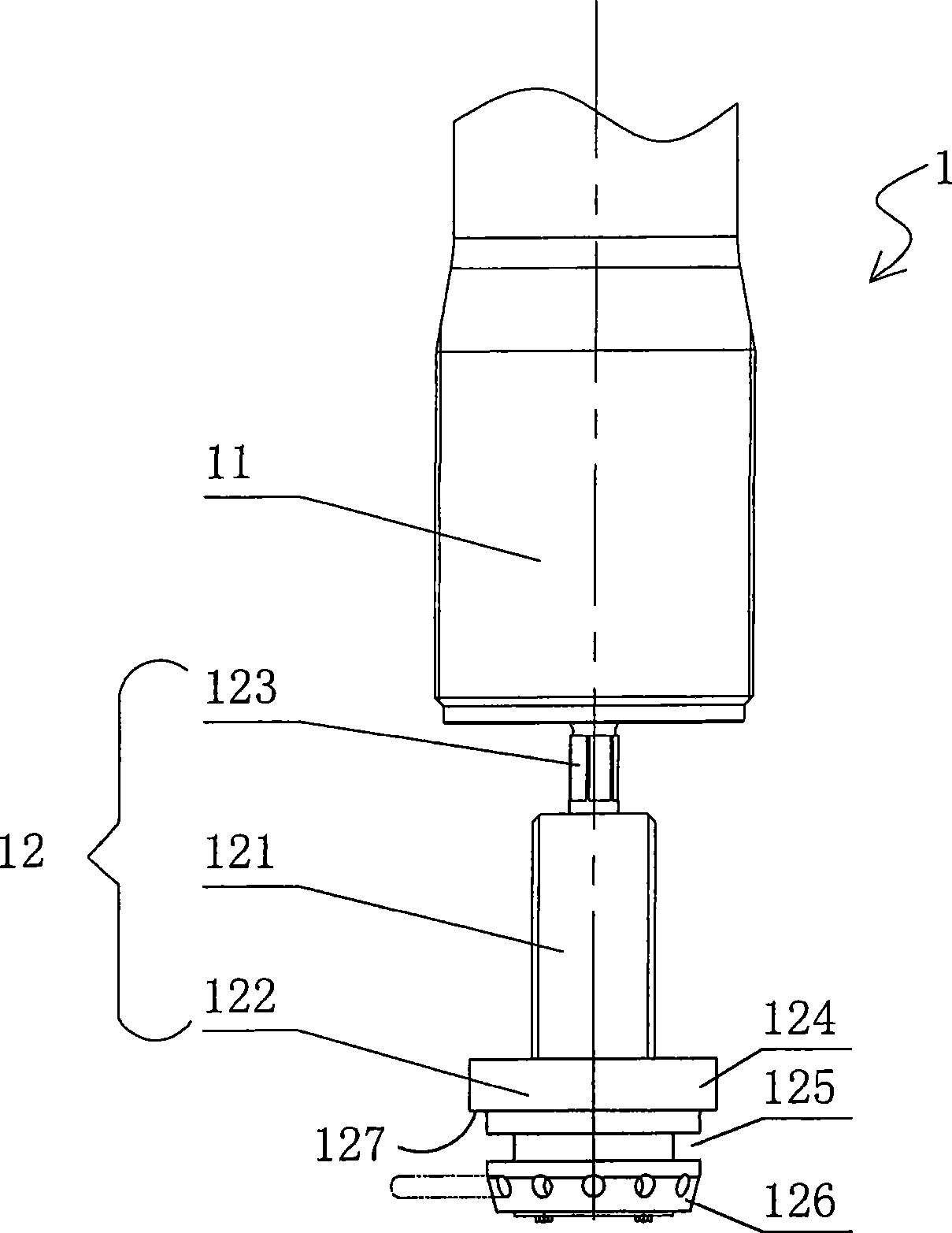
[0035] like figure 1 — Figure 4 As shown, the installation tool for the lower prestressed nut proposed by the present invention includes a rising screw 1 and a rotating table 2 . The ascending screw 1 includes a pull rod 11 and a connecting assembly 12, and the connecting assembly 12 is fixedly connected to the lower part of the pull rod 11. The turntable 2 comprises a lower prestressed nut 21 and a positioning assembly 22, the positioning assembly 22 is connected to the lower part of the lower prestressed nut 21, and the positioning assembly 22 and the lower prestressed nut 21 are fixed to each other in the circumferential direction, that is, they cannot rotate mutually; A through accommodating space 23 is longitudinally provided in the center. The ascending screw 1 is arranged in the accommodating space 23 of the turntable 2 so as to move up and down; the lower prestressing nut 21 and the pull rod 11 can be screwed together through the mutual cooperation of the connecting...

Embodiment approach 2

[0050] In this embodiment, the bearing 224 and the bearing seat 223 of Embodiment 1 are not included, but the above-mentioned guide rail is provided at the lower part of the positioning bracket, and the snap ring 222 is directly provided on the guide rail at the lower part of the positioning bracket. At this time, the positioning bracket 221 needs to have a supporting surface, so that the shoulder of the stepped matching portion 124 can push against the supporting surface for positioning.

[0051] The installation tool of this embodiment has a simple structure, reduced manufacturing cost and reduced installation time due to the lack of components such as bearings and bearing housings.

[0052] Other structures, working principles, and beneficial effects of this embodiment are the same as those of Embodiment 1, and will not be repeated here.


PUM


Abstract

The invention discloses a installation tool of a lower pre-stressed nut, which comprises a lifting screw rod including a tie rod and a connecting component fixedly connected on the lower part of the tie rod, and a rotary table including the lower pre-stressed nut and a positioning component connected on the lower part of the lower pre-stressed nut; the positioning component and the lower pre-stressed nut are mutually fixed along the circumference direction; the center of the rotary table is equipped with a run-through holding space along the vertical direction; the lifting screw rod can move up and down to be matched with the holding space arranged on the rotary table; through the mutual matching of the connecting component and the positioning component, the lower pre-stressed nut can be connected with the tie rod by a thread. The installation tool of the lower pre-stressed nut can conveniently connect the lower pre-stressed nut with the rod, and the installation effect thereof is good, thus reducing the labor strength and the installation time, and improving the work efficiency.

Description

technical field [0001] The invention relates to an installation tool for a lower prestressed nut. Background technique [0002] At present, more and more prestressed frame structures with high rigidity and good stress state are used on hydraulic presses. In this structure, there are tie rods with threads processed at both ends. The lower prestressed nuts are cooperatingly arranged, and the pull rod needs to pass through the upper beam, the column and the lower beam, and the two ends are respectively connected and fixed by the upper and lower prestressed nuts, so that they are integrated. [0003] When the traditional lower prestressed nut is installed, it is necessary to manually or use auxiliary tools such as a jack to lift the nut and manually tighten it on the lower end of the tie rod. Due to the high precision of thread processing of prestressed nuts and tie rods, abrasion of threaded parts should be avoided. However, it is very easy to damage the thread of the tie rod...

Claims


Application Information

Patent Timeline
Patent Type & Authority Applications(China)
IPC IPC(8): B23P19/06
Inventor 王旭林怀峰曹英强黄木罗寅生谢宇
Owner MCC CAPITAL ENGINEERING & RESEARCH
Why Eureka
Try Eureka