
Method and apparatus for configuring multifunctional electrolytic set tools wagon

A multifunctional unit and configuration device technology, which is applied to cranes, transportation and packaging, and traveling bridge cranes, etc., can solve problems such as restricting the competitiveness of electrolysis multifunctional units, inconvenient operation for operators, and inability to operate tools for positioning. To achieve the effect of novel product structure and appearance, convenient operation and simple structure

Active Publication Date: 2014-03-26
GUIYANG AL-MG DESIGN & RES INST +1
View PDF5 Cites 0 Cited by
  • Summary
  • Abstract
  • Description
  • Claims
  • Application Information

AI Technical Summary

Problems solved by technology

[0002] At present, the tool trolleys used in the electrolytic multifunctional units produced in my country are basically based on the traditional foreign technology model, and there is no major change in structure. The tool is set on a slewing mechanism, and its control room is fixed. The operator sits in the fixed control room and controls the movement of the slewing mechanism and the tool through cable control. Since the control room cannot rotate with the slewing mechanism of the operating tool, Therefore, it is very inconvenient for the operator to operate, and it is difficult to carry out accurate and fast tool positioning operation, and the work efficiency is very low; in addition, the existing electrolytic multifunctional unit tool trolley also has a relatively complicated structure, fewer functions, and is difficult to install and maintain. Inconvenience and other shortcomings, which not only cannot meet the needs of production, but also restrict the competitiveness of the electrolytic multifunctional units produced in my country in the international market

Method used


Image

  • Method and apparatus for configuring multifunctional electrolytic set tools wagon
  • Method and apparatus for configuring multifunctional electrolytic set tools wagon
  • Method and apparatus for configuring multifunctional electrolytic set tools wagon

Examples


Embodiment Construction

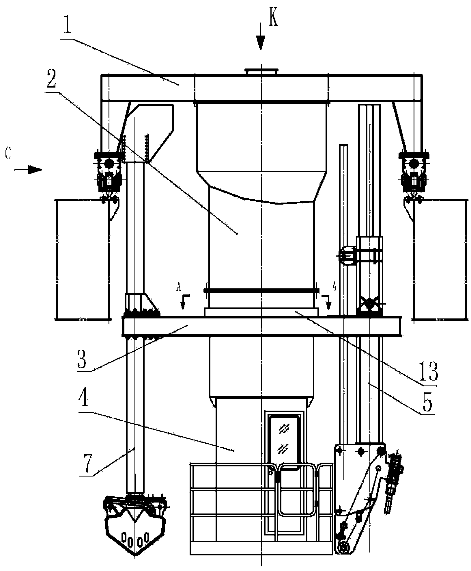
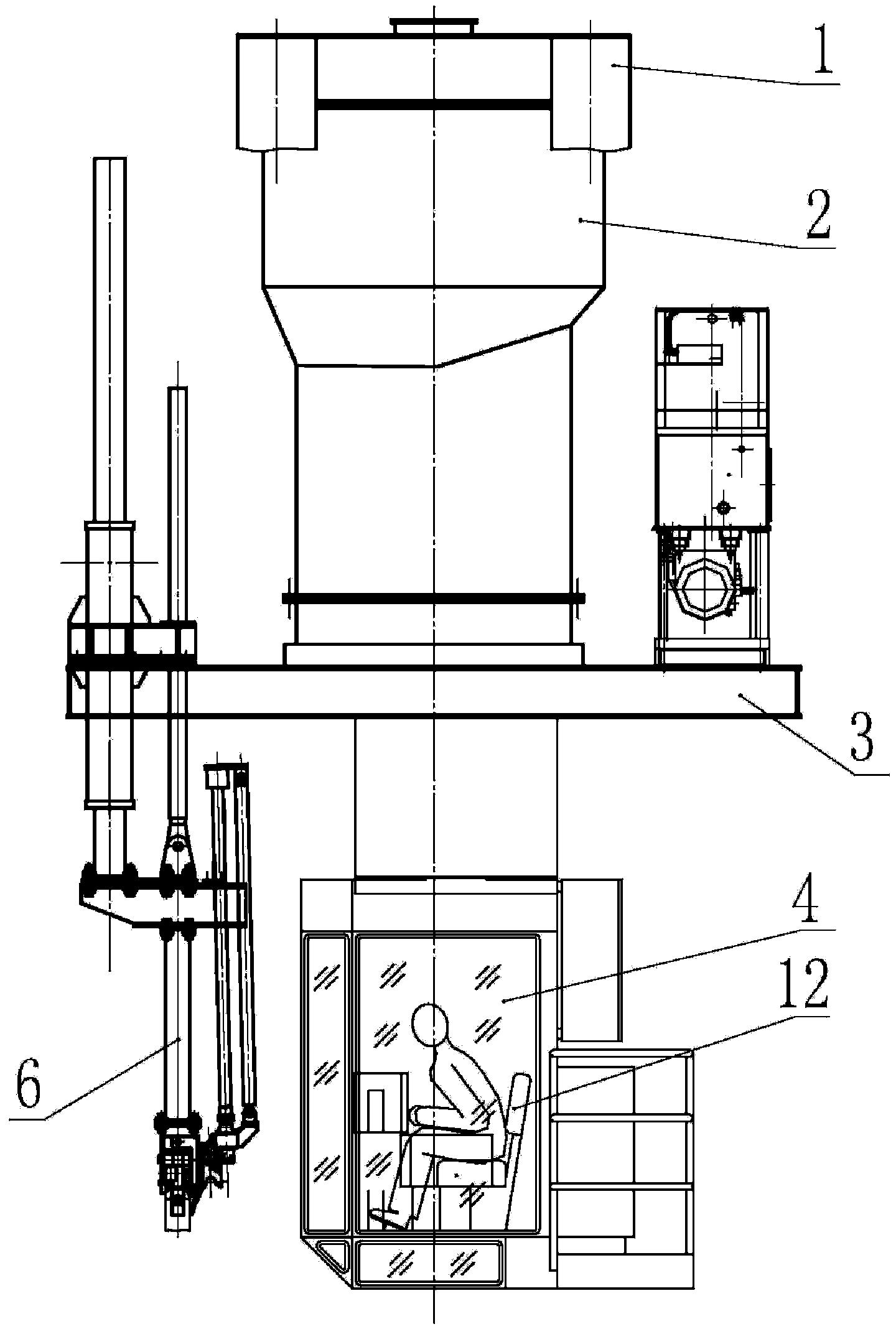
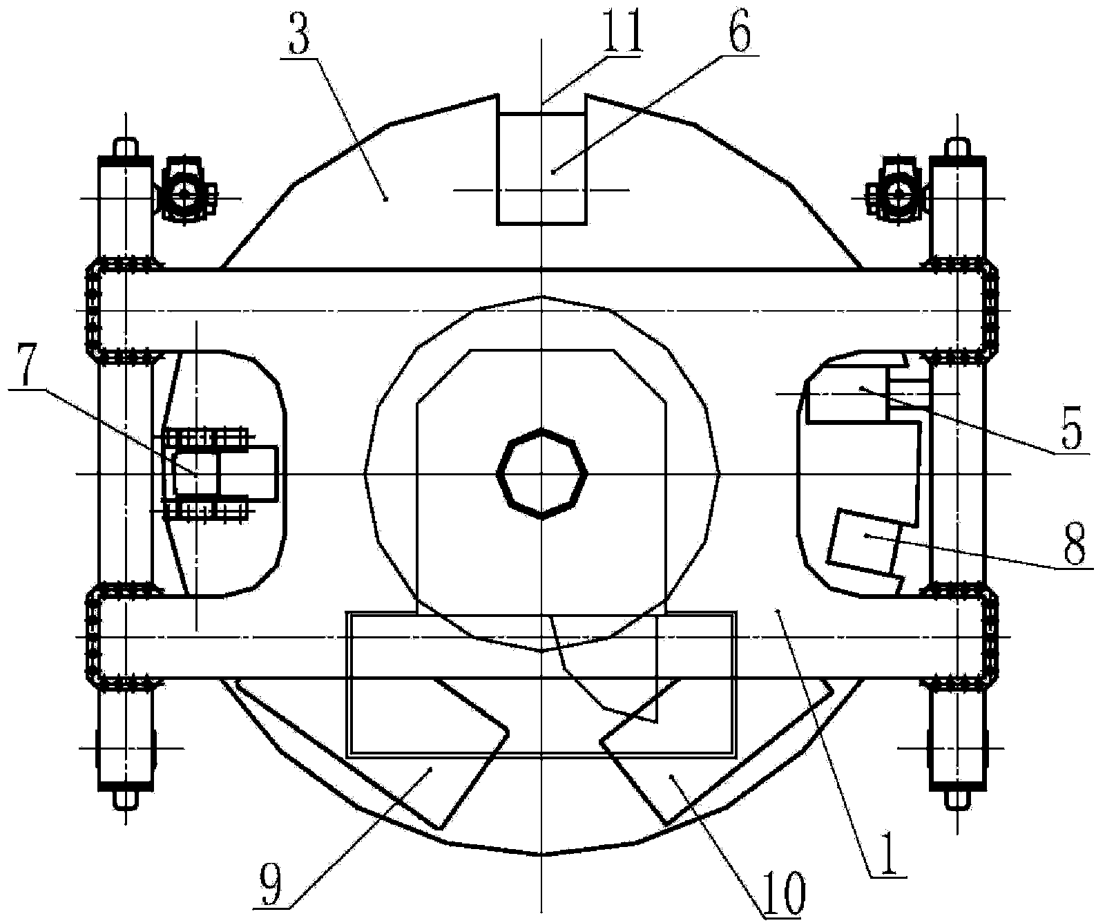
[0020] The tool trolley for the electrolytic multifunctional unit of the present invention will be further described in detail below in conjunction with the accompanying drawings and embodiments, but it is not used as a basis for any limitation of the present invention.

[0021] Embodiment of the present invention: when making the tool trolley of the electrolytic multifunctional unit, it is produced according to a configuration method of the tool trolley of the electrolytic multifunctional unit of the present invention, that is, the material box is fixed on the frame of the tool trolley of the electrolytic multifunctional unit, The material box is fixed in the center of the tool trolley and cannot be rotated, and a rotatable tool turntable is set at the lower part of the material box, and the control room is fixed below the tool turntable so that the center line of the control room is located on the rotation center line of the tool turntable. It can rotate together with the too...


PUM


Abstract

A method for configuring the tool set of a multifunctional trolley system for electrolysis is disclosed, wherein, a bin for starting materials is fixed on the frame of the trolley system so that the bin is fixed in the center of the trolley system without rotation; a rotating turntable for suspending tools is arranged below the bin and a control cab is fixed below the turntable, thus the control cab has the coincident centerline with the turntable and can rotate with the turntable; four tools, i.e. a crust breaking tool, an anode replacement tool, an anode pit cleaning grab and a charging device are arranged around the control cab and are fixed on the turntable; a manipulating platform capable of rotating within ±90 degree is arranged inside the control cab such that the centerline of the platform is located at the rotary center of the turntable; a hydraulic station and an electric controlling cabinet for controlling the actions of the trolley system and each tool are all fixed on the turntable. An apparatus obtained by the above-said configuring method is also disclosed.

Description

technical field [0001] The invention relates to a method and a device for configuring a tool trolley of an electrolytic multifunctional unit, and belongs to the technical field of a tool trolley of an electrolytic multifunctional unit used in the aluminum electrolysis industry. Background technique [0002] At present, the tool trolleys used in the electrolytic multi-function units produced in my country are basically based on the traditional technology of foreign countries, and there is no major change in structure. The tool is set on a slewing mechanism, and its control room is fixed. The operator sits in the fixed control room and controls the movement of the slewing mechanism and the tool through cable control. Since the control room cannot rotate with the slewing mechanism of the operating tool, Therefore, it is very inconvenient for the operator to operate, and it is difficult to carry out accurate and fast tool positioning operation, and the work efficiency is very low;...

Claims


Application Information

Patent Timeline
Patent Type & Authority Patents(China)
IPC IPC(8): C25C3/06C25C3/20C25C3/10C25C3/14
CPCC25C3/14B66C17/06
Inventor 陈才荣孔丽珍吕光华段晓明柳盛飞刘红晏燕
Owner GUIYANG AL-MG DESIGN & RES INST
Features
  • Generate Ideas
  • Intellectual Property
  • Life Sciences
  • Materials
  • Tech Scout
  • Unparalleled Data Quality
  • Higher Quality Content
  • 60% Fewer Hallucinations
Learn More