Radiation element structure for wind band dual polarization antenna

A dual-polarized antenna and radiating element technology, which is applied to antenna unit combinations, antennas, electrical components and other directions with different polarization directions, can solve the problems of difficult array design, high cost of radiator, and increase in size of radiator. The effect of improving return loss, stable and reliable structure, and improving balance

Active Publication Date: 2009-08-12
MOBILE ANTENNA TECH SHENZHEN +5
View PDF3 Cites 54 Cited by
  • Summary
  • Abstract
  • Description
  • Claims
  • Application Information

AI Technical Summary

Problems solved by technology

However, in practical applications, in order to meet the requirements of anti-matching, the above-mentioned structure will greatly increase the size of the radiation s

Method used


Image

  • Radiation element structure for wind band dual polarization antenna
  • Radiation element structure for wind band dual polarization antenna
  • Radiation element structure for wind band dual polarization antenna

Examples


Embodiment 1

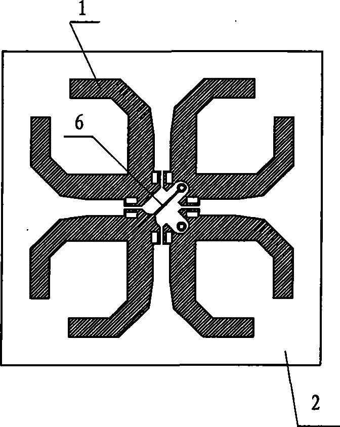
[0039] This embodiment is an embodiment of the structure of the surface radiation unit adopting the feeding mode of the flat conductor.

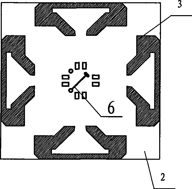
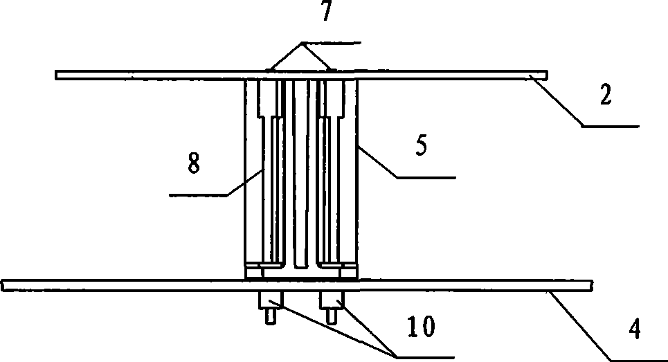
[0040] see Figure 1a — Figure 1c , the structure of the surface radiation unit in this embodiment includes a surface radiation unit 1, a dielectric plate 2, a reflector 4 and a feed support 5, and also includes a parasitic metal ring piece 3. In this embodiment, the surface radiation unit 1 includes a symmetrical Two pairs of half-wave element arms arranged obliquely at 45° in a cross, the arm shape is similar to a "U"-shaped structure, the feed section 6 is located in the middle of each element arm, one end is connected to the element arm, and the other end is connected to the flat conductor The convex parts of 8 are connected; the parasitic metal ring piece 3 is a semi-ring metal piece structure, located at the ends of two adjacent polarized array arms. In this way, the open circuit of the high frequency itself in its 1 / 4 wavelength str...

Embodiment 2

[0044] This embodiment is an embodiment of the structure of the surface radiation unit adopting the circuit board conductor feeding method.

[0045] see Figure 2a — Figure 2g The structure of the surface radiation unit in this embodiment includes a surface radiation unit 11 , a dielectric plate 12 , a reflection plate 14 , and a feed support 15 , and also includes a parasitic metal ring 13 . In this embodiment, the parasitic metal ring sheet 3 is also a semi-annular metal sheet structure, and the surface radiation unit 11 includes two pairs of half-wave element arms that are symmetrical and obliquely arranged in a cross at 45°. The arm shape is similar to a "V"-shaped structure, and is capacitively connected at both ends of the "V"-shaped tail. The parasitic metal ring piece 3 is located at the end of two adjacent polarized array arms. The surface radiation unit 11 and the parasitic metal ring piece 13 They are respectively etched on the front and back sides of the dielect...


PUM


Abstract

The invention provides a radial element structure of a broadband bipolarized antenna, which comprises a surface radiation unit, a medium plate, a feeding support and a reflecting plate; the surface radiation unit comprises array arms of semi-wave arrays; the feeding support is positioned between the medium plate and the reflecting plate; the invention also comprises a parasitic structure which is arranged at the bottom end of the array arm of the surface radiation unit to allow two adjacent array arms to be in capacitive joint; and the surface radiation unit and the parasitic structure are adhered on two sides of the medium plate respectively. The radial element structure can improve the balance of the arrays, effectively improves the crossed polarization property and strengthens the directivity of radiation in the direction of +/-60 degrees; and the radial element structure improves the back wave loss and the isolation degree of the arrays. The radial element structure has a more stable and reliable structure and is easier to be rapidly assembled and welded as an independent part.

Description

technical field [0001] The invention relates to the field of mobile communication base station antennas, in particular to a broadband dual-polarized antenna radiation element structure. Background technique [0002] At present, most of the elements of dual-polarized antennas use two pairs of orthogonal half-wave oscillator structures. This structure realizes the field orthogonality of the two pairs of half-wave elements relatively intuitively, such as vertical and horizontal, with an oblique angle of ±45°, so that Realize the dual polarization of the antenna element. The ideal orthogonality is very important for the polarization separation of the two polarizations of the dual-polarization element and the efficiency of the dual-polarization antenna. The quality of its orthogonality is usually evaluated by cross-polarization resolution or cross-polarization ratio . The currently commonly used evaluation indicators are: the cross-polarization ratio of the main axis and the cr...

Claims


Application Information

Patent Timeline
IPC IPC(8): H01Q21/24H01Q19/10
Inventor 苏卫侯小强龚凤英
Owner MOBILE ANTENNA TECH SHENZHEN
Why Eureka
Try Eureka