
Gyroscopic apparatus

A technology of limiting device and torque, applied in the field of motors

Active Publication Date: 2009-08-12
SIM NETHERLANDS
View PDF0 Cites 2 Cited by
  • Summary
  • Abstract
  • Description
  • Claims
  • Application Information

AI Technical Summary

Problems solved by technology

When the rotational speed of the body reaches a critical value, there is still rotation of the first axis about the output axis, but now there is no longer any rotation of the first axis about the tilt axis

Method used


Image

  • Gyroscopic apparatus
  • Gyroscopic apparatus
  • Gyroscopic apparatus

Examples


Embodiment Construction

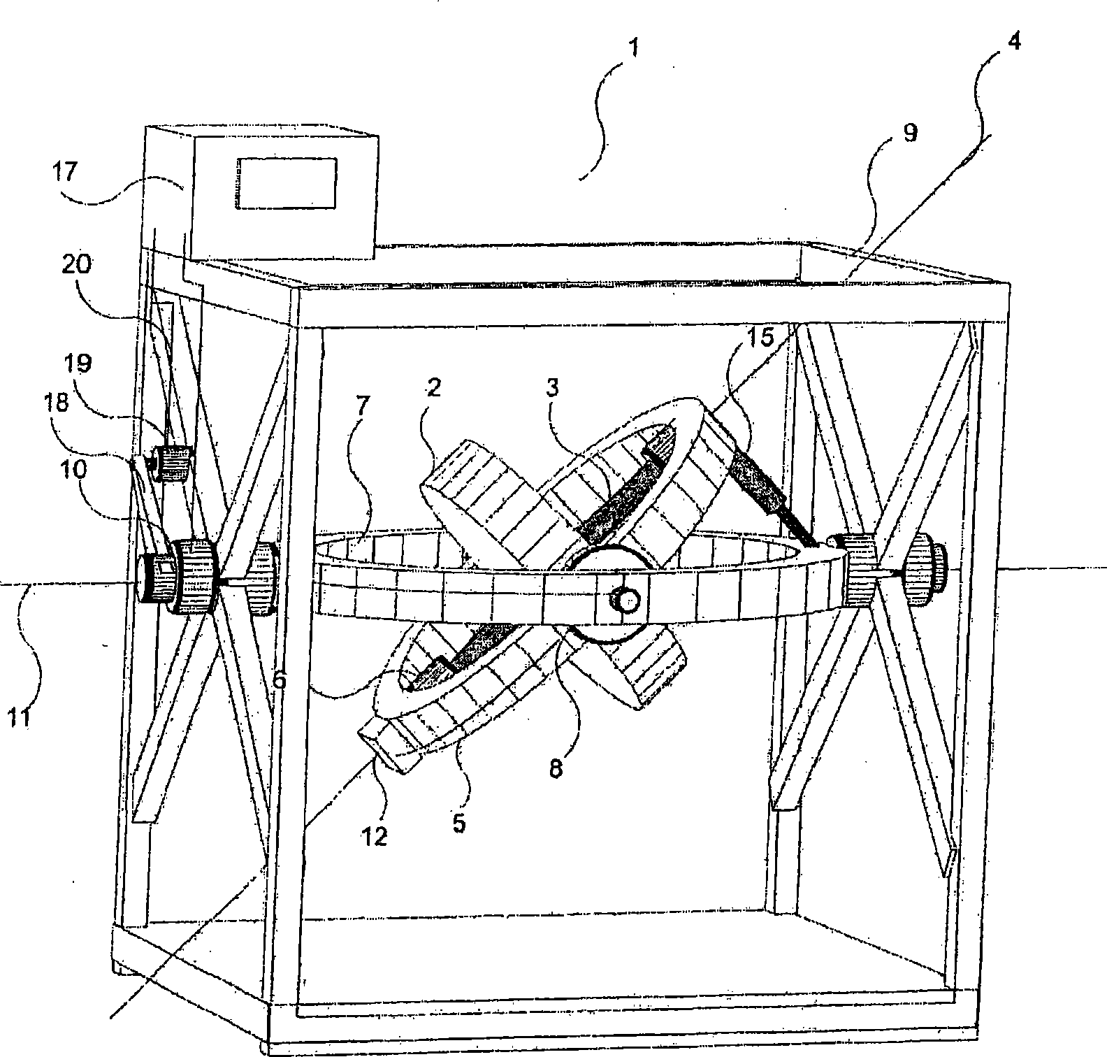
[0043] Such as figure 1 As shown, the motor 1 comprises a body in the form of a solid cylindrical wheel 2 coaxially mounted on a rotary shaft 3 for consequent rotation about a first axis 4 . The rotating shaft 3 is mounted in an inner bracket 5 via an inner support / bearing 6 . The inner bracket 5 is mounted in the outer bracket 7 by means of an outer support 8 so as to limit the rotation about an axis - this axis is called the tilt axis in the following, while the second bracket 7 is mounted in the frame 9 by a frame support 10, so that The second bracket 7 is rotatable relative to the frame 9 about a second axis 11 constituting the output axis of the motor 1 .

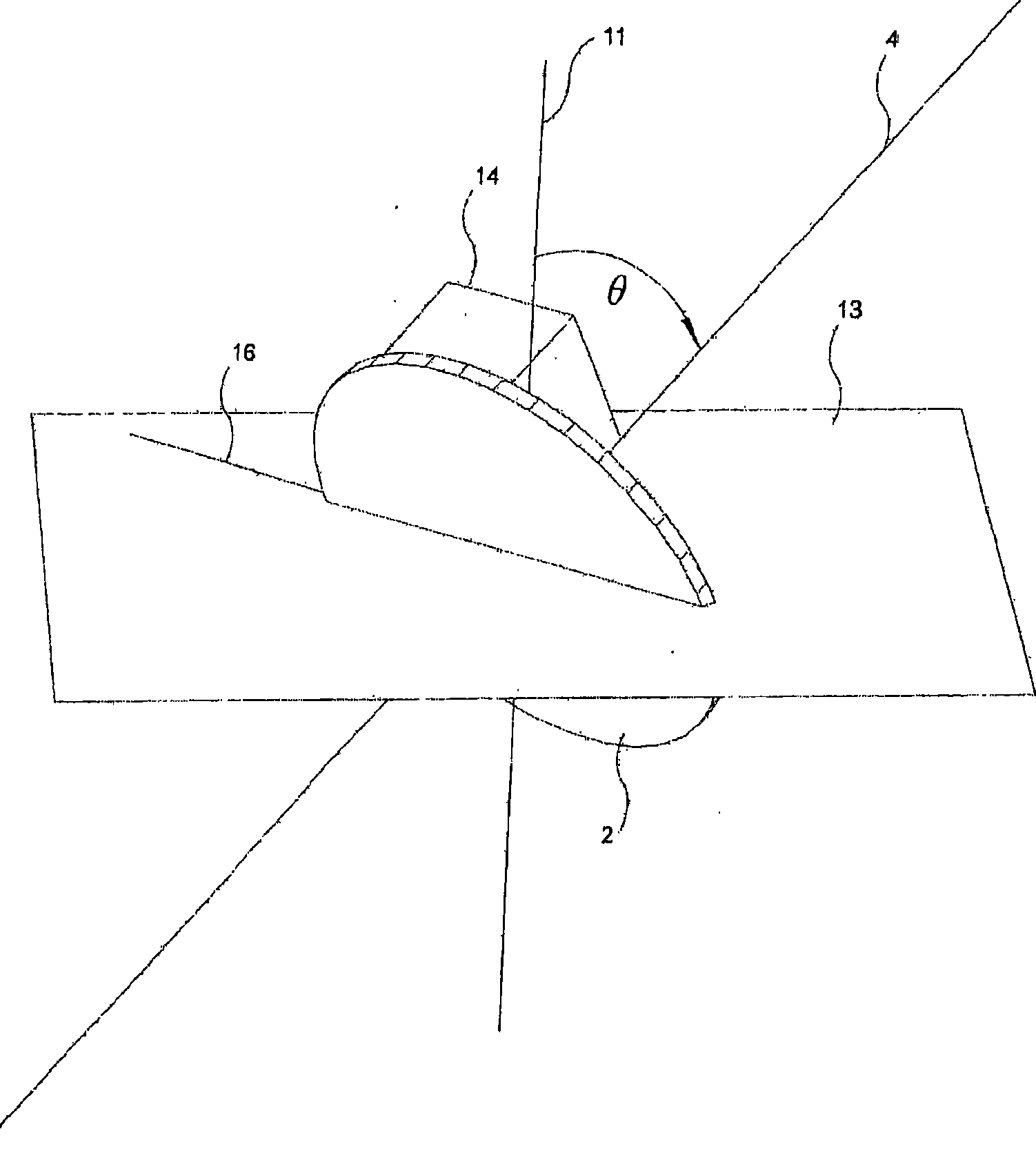
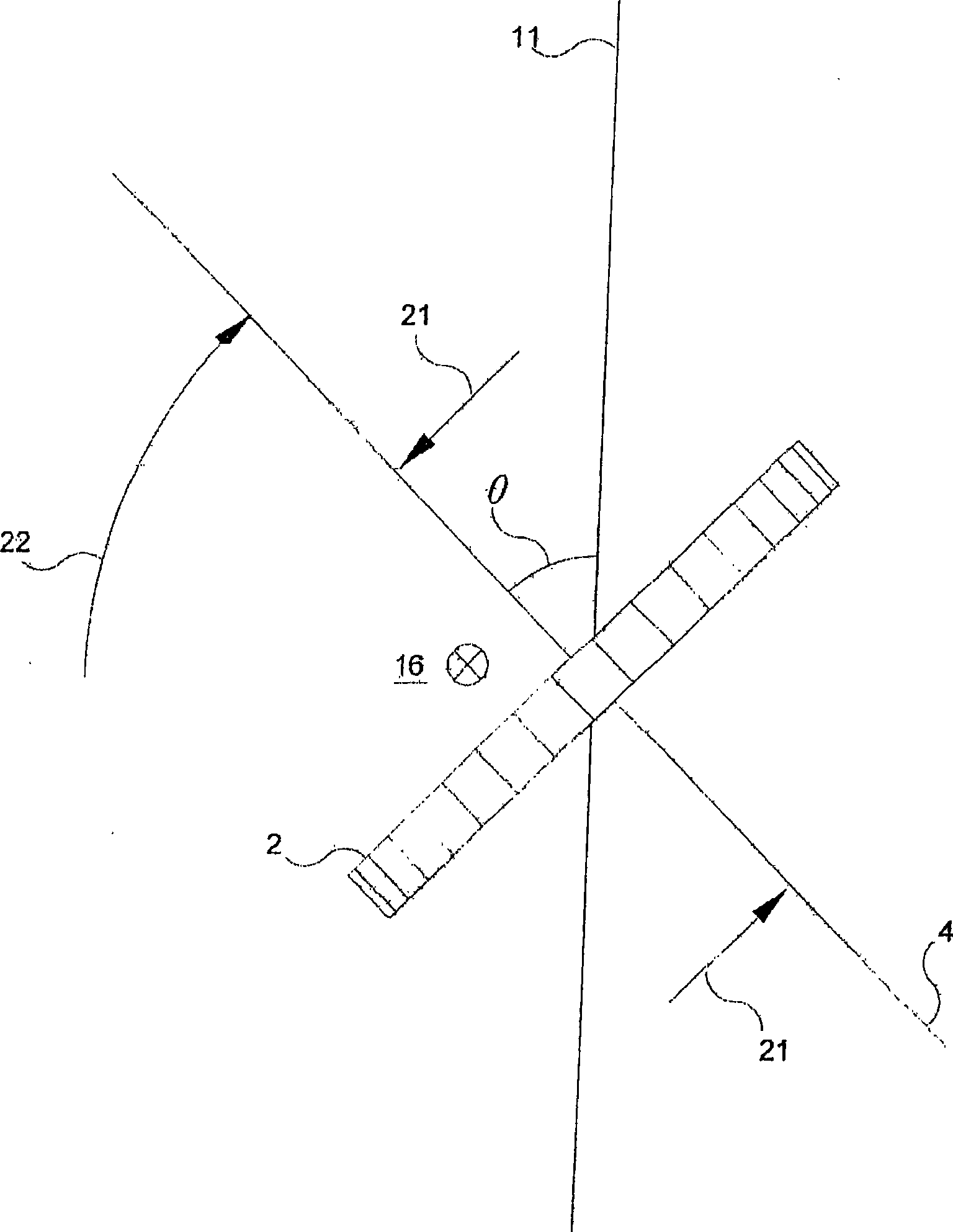
[0044] The rotational axis 3 of the wheel 2 may be rotated about the first axis 4 by an electric motor 12 or other input power source. Electric motor 12 may be powered by batteries. The rotating shaft 3 is installed at an inclination angle θ with respect to the output axis 11 of the motor 1, and the inclination ang...


PUM


Abstract

The present invention relates to motors and, more specifically to rotary motors which can supply output motive power about an output axis in response to input rotary power about a different axis. A motor (1) comprises a wheel (2) mounted on a shaft (3) for rotation about a first axis (4). The shaft (3) is additionally mounted for rotation about both an inclination axis (16) and the output axis (11) of the motor (1).

Description

technical field [0001] The present invention relates to motors, and more particularly to rotary motors, which can supply output power about a different output axis in response to input rotary power about one axis. Background technique [0002] When a torque acts on a rotating body about an axis perpendicular to the axis of rotation, it causes the axis of rotation to rotate itself about another axis which is perpendicular both to the axis of the applied torque and to the axis of rotation . This principle is well known. [0003] The inventors of the present invention have discovered that when the axis of rotation of the body (hereinafter referred to as the first axis) constrains itself about (a) a second axis forming an acute angle with the axis of rotation of the body (hereinafter referred to as the output axis) and ( b) When a third axis substantially perpendicular to the first and second axes (hereafter referred to as the tilt axis) rotates, the torque applied around the ...

Claims


Application Information

Patent Timeline
Patent Type & Authority Applications(China)
IPC IPC(8): B64C17/06G01C19/00F03G3/08
CPCF03G3/08F03H99/00Y10T74/1254Y10T74/1214B64C17/06G01C19/00H02K19/02
Inventor M·N·奥兹特克
Owner SIM NETHERLANDS
Learn More