

Diversity antenna system with electrical tilt
An antenna system, electrical tilt technology, applied in diversity/multi-antenna systems, antennas, combinations of antenna units with different polarization directions, etc.
- Summary
- Abstract
- Description
- Claims
- Application Information
AI Technical Summary
Problems solved by technology
Method used
Image

Examples
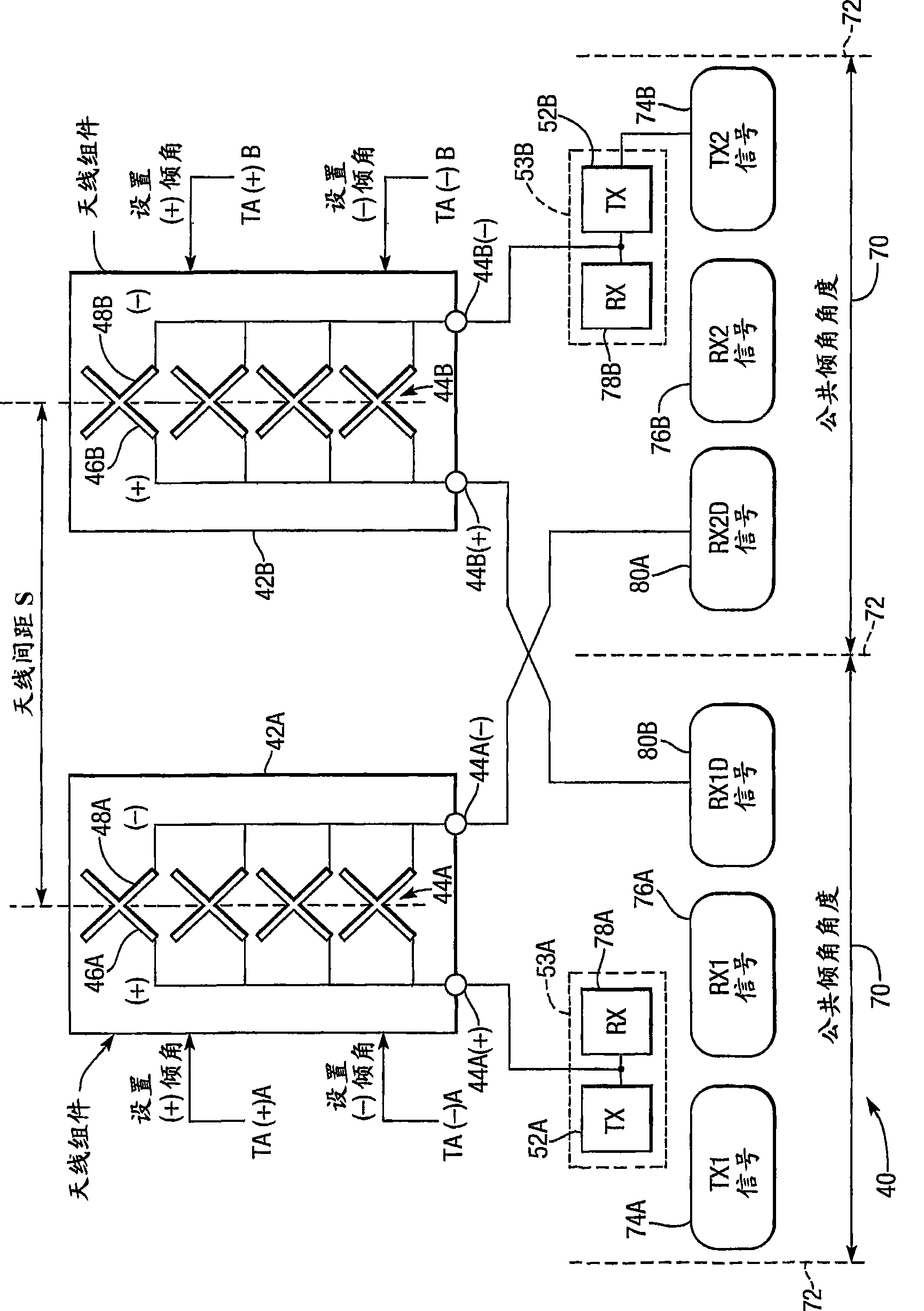
Embodiment 440
[0125] Embodiment 440 requires only ten filters 456A, 456B, etc. due to the use of the third feeder F63 for the space diversity receive signal. The third feeder F63 does not transmit the transmit signal with much higher power than the receive signal, so this feeder F63 may have a smaller diameter and higher loss than the first and second feeder F61 and F62. The acceptable power loss of the third feed line F63 is limited by the gain and dynamic range of the LNAs 464A and 462B and the height at which the antenna assemblies 454A and 454B are mounted on a conventional antenna support pole (not shown). A third feeder F63 may be enclosed in a common sheath (not shown) with one of the first and second feeders F61 and F62 to simulate a dual feeder arrangement.
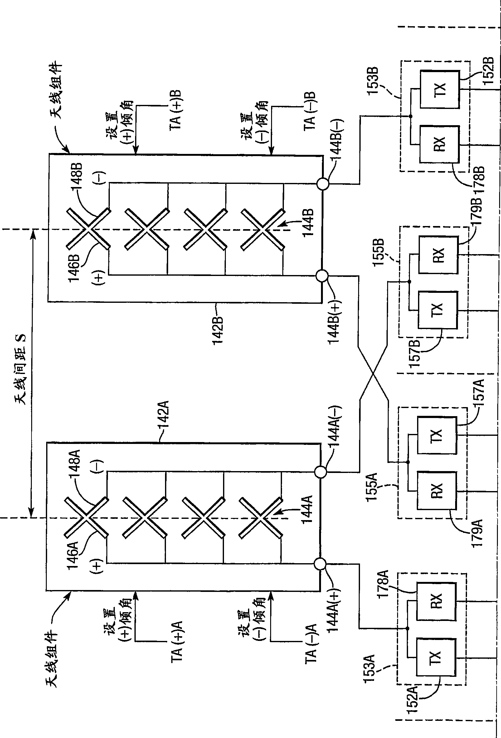
[0126] now refer to Figure 7 , shows yet another antenna system 540 of the present invention, which is referenced Figure 6 A simplified version of the antenna system described. It is suitable for use with adjacent frequen...
PUM
 Abstract
Description
Claims
Application Information