Pneumatic pressure low-pressure alarming device

A low-pressure alarm and pressure technology, used in alarms, measuring devices, measuring fluid pressure, etc., can solve problems such as high cost and inability to use ventilators, and achieve the effects of low cost, simple structure and easy implementation.

Inactive Publication Date: 2009-08-19
王中
View PDF0 Cites 10 Cited by
  • Summary
  • Abstract
  • Description
  • Claims
  • Application Information

AI Technical Summary

Problems solved by technology

This method belongs to the electronic control alarm mechanism, which requires power supply, and requires the cooperation of electronic devices such as pressure sensors and single-chip microcomputers. Therefore, it is restricted by power supply conditions and cannot be used for pneumatic and air-controlled ventilators, and the cost is high.

Method used


Image

  • Pneumatic pressure low-pressure alarming device
  • Pneumatic pressure low-pressure alarming device
  • Pneumatic pressure low-pressure alarming device

Examples


Embodiment Construction

[0021] The present invention will be further described below in conjunction with the embodiments (drawings):

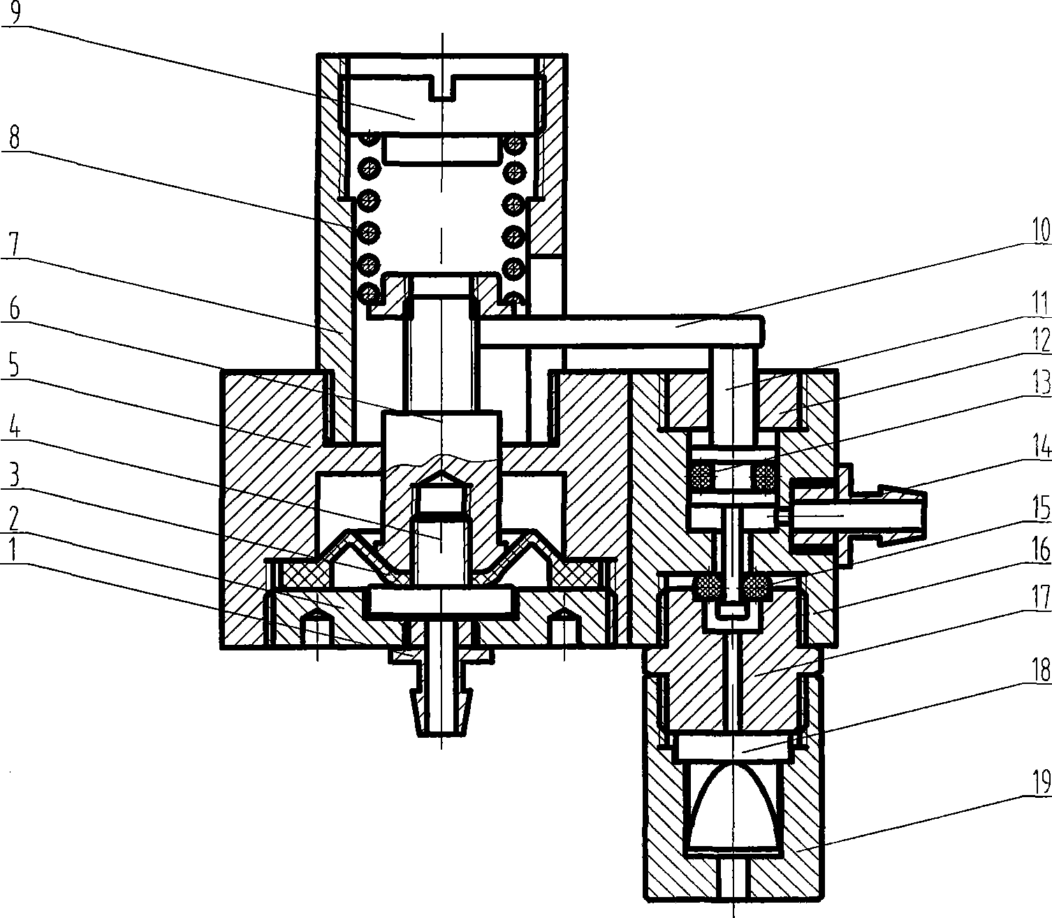
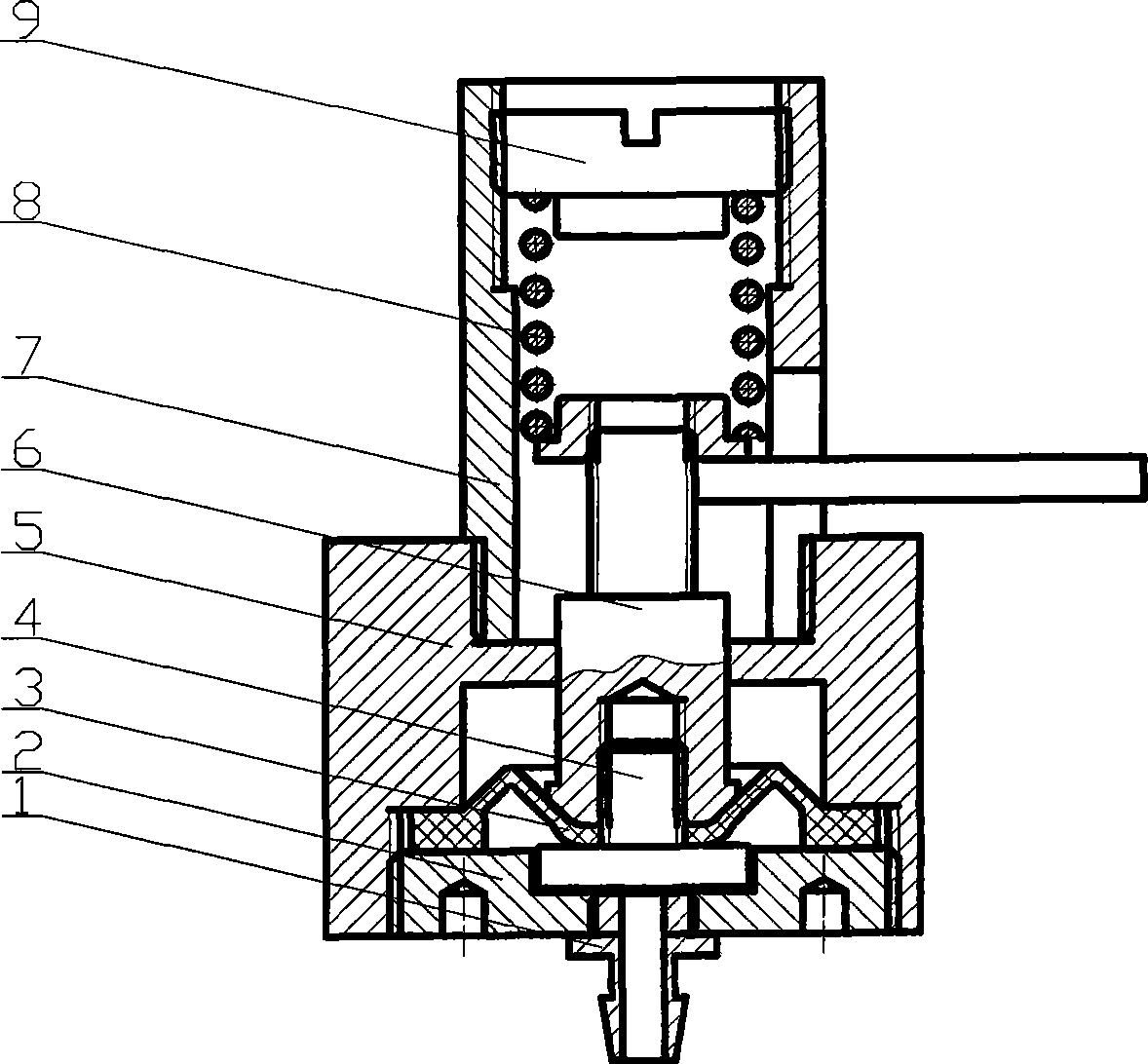
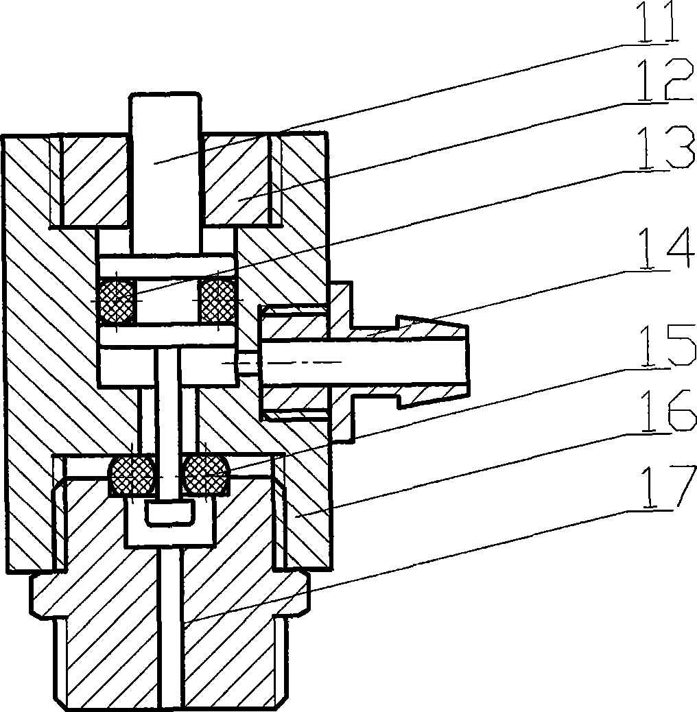
[0022] Such as figure 1 As shown, the pneumatic pressure low-pressure alarm device of the present invention includes three parts: a pressure detection mechanism, a micro switch valve and an alarm mechanism. Through the three-way, two channels of gas are output from the gas source, one is sent to the gas source inlet of the pressure detection device to detect the pressure of the gas source, and the other is sent to the gas source inlet of the micro switch valve as the driving airflow of the alarm device.

[0023] Such as figure 1 , figure 2 As shown, the pressure detection mechanism includes an outer shell composed of an upper shell 7 and a lower shell 5, which is screwed together by a threaded connection, and is provided with upper and lower cavities, and is sealed under the outer shell by a lower end cover 2. The diaphragm 3 in the cavity is formed by the diaphragm 3 ...


PUM


Abstract

The invention relates to a pneumatic low pressure warning device, which is characterized in that the device comprises a pressure detection mechanism, a micro switching valve and a warning mechanism; and two paths of gas are output through a tee from a gas source, wherein one path is delivered to a gas source inlet of the pressure detection mechanism to detect the pressure of the gas source, and the other path is delivered to a gas source inlet of the micro switching valve and taken as driving gas flow of the warning device. Compared with the prior art, the pneumatic low pressure warning device has the advantages that the warning device needs no power source, is completely driven by the gas source, can be used as a low pressure warning mechanism in a full pneumatic control respirator or other pneumatic products, and has high precision, simple structure, low cost and easy realization.

Description

Technical field [0001] The invention relates to a medical ventilator, in particular to a pneumatic pressure low-pressure alarm device that can judge the pressure of a pneumatic device without a power source and send out an alarm signal when the pressure is low. Background technique [0002] The low-pressure alarm mechanism of the ventilator in the prior art collects the pressure signal through the pressure sensor and sends it to the single-chip microcomputer for comparison with the set alarm value. When the alarm condition is reached, the buzzer is controlled to send an alarm signal. This method belongs to an electronically controlled alarm mechanism, which requires power supply, and requires electronic devices such as pressure sensors to cooperate with a single-chip microcomputer. Therefore, due to power supply conditions, it cannot be used for pneumatically controlled ventilators, and the cost is high. Summary of the invention [0003] The purpose of the present invention is t...

Claims


Application Information

Patent Timeline
IPC IPC(8): A61M16/00G08B21/18G08B3/06G01L19/12
Inventor 王中
Owner 王中
Why Eureka
Try Eureka