Electrohydraulic composite braked brake valve for vehicle line control and control method thereof

A brake valve, electronic controller technology, applied in the direction of brakes, brake components, vehicle components, etc., can solve problems such as inability to control brake line pressure

Inactive Publication Date: 2009-08-19
TONGJI UNIV
View PDF0 Cites 29 Cited by
  • Summary
  • Abstract
  • Description
  • Claims
  • Application Information

AI Technical Summary

Problems solved by technology

[0003] The purpose of the present invention is to solve the technical problem that the existing hydraulic brake system cannot control the pressure of the brake pipeline, and to provide a brake valve and its con

Method used


Image

  • Electrohydraulic composite braked brake valve for vehicle line control and control method thereof

Examples


Embodiment Construction

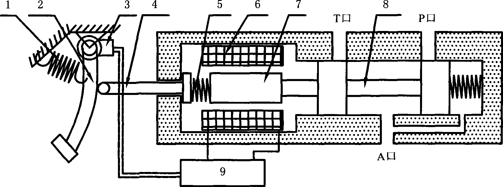
[0014] The present invention will be further described below in conjunction with the embodiments shown in the accompanying drawings.

[0015] The electromechanical dual-purpose brake valve of the present invention includes a pedal feeling spring 1, a brake pedal 2, a pedal position sensor 3, a mechanical action end 4, a mechanical action spring 5, a proportional electromagnetic coil 6, an armature 7, a brake spool 8, an electronic The controller 9 mainly adds a pedal position sensor 3, an electronic controller 9, a proportional electromagnetic coil 6, and an armature 7 to the existing brake valve. The pipeline pressure of the brake system is controlled by the electromechanical dual-purpose brake valve. The brake spool 8 is a direct-acting structure, and the action of the spool can be realized independently by two sets of structures of the proportional electromagnetic coil 6 and the mechanical action end 4 . Wherein the sensor 3 is installed on the pedal 2, when the driver brak...


PUM


Abstract

The invention relates to a brake valve for vehicle wire control electro-hydraulic brake and a control method thereof, which comprise a pedal sensing spring, a brake pedal, a mechanical action end, a mechanical action spring and a brake valve core. The brake valve also comprises a pedal position senor, an electronic controller, an electromagnetic coil, and an armature, wherein the pedal position senor is arranged on the pedal, the armature is arranged on a decompressed valve core near the end of the brake pedal, the two sides of the armature are provided with corresponding electromagnetic coils, and the sensor, the electronic controller and the electromagnetic coil are connected by a lead. The senor senses the displacement of the pedal and generates a corresponding signal and sends the signal to the electronic controller to supply corresponding current to coils, and the coils generate an electromagnetic force to control the movement of the brake valve core to realize brake; when an electrical fault occurs, the device can also carry out mechanical brake when a drive tramples the pedal deeply. The brake valve is simple in structure, can realize wire control of the brake pipe fluid pressure, and has the capacity of mechanical backup brake under the condition of the electrical fault.

Description

technical field [0001] The invention relates to a braking valve, in particular to an electromechanical dual-purpose braking valve for vehicle wire-controlled hydraulic braking. Background technique [0002] Current electric vehicles or hybrid vehicles with electric drive all have the capability of electric motor regenerative braking. However, the traditional hydraulic braking system has no ability to control the pressure of the brake line, and the hydraulic braking force can only increase proportionally with the driver's pedal force. Therefore, this kind of braking system cannot fully utilize the regenerative braking capability of the motor, and cannot give full play to the advantages of the motor-driven vehicle in realizing the recovery of braking energy. Contents of the invention [0003] The purpose of the present invention is to solve the technical problem that the existing hydraulic brake system cannot control the pressure of the brake pipeline, and to provide a brak...

Claims


Application Information

Patent Timeline
IPC IPC(8): B60T7/06B60T15/04
Inventor 孙泽昌卓桂荣刘清河
Owner TONGJI UNIV
Why Eureka
Try Eureka