Cavity structure of ECR plasma sputtering apparatus

A sputtering device and plasma technology, which are applied in sputtering coating, ion implantation coating, metal material coating process and other directions, can solve the problems of high cost, unfavorable equipment use and high energy consumption when disassembling the target material, etc. Low cost, satisfying large-scale industrial production, and simple cavity structure

Inactive Publication Date: 2011-04-06
XI AN JIAOTONG UNIV
View PDF0 Cites 0 Cited by
  • Summary
  • Abstract
  • Description
  • Claims
  • Application Information

AI Technical Summary

Problems solved by technology

[0003] At present, in the field of thin film preparation by sputtering, targets with fixed chemical composition are generally used. When studying and analyzing the influence of different elements on sputtering products (films), targets with different element contents are usually made. Then each To analyze a certain element content ratio, it is necessary to make a target material, which is not only expensive, but also frequently disassembles the target material, which is not conducive to the use of equipment, and the production efficiency is low; The design of the multi-layer structure (such as sputtering to prepare multi-layer optical films of different materials), put different targets in the two sputtering chambers and sputter in time to realize the multi-layer structure, but the double-cavity The cost is high and the energy consumption in the sputtering process is large

Method used


Image

  • Cavity structure of ECR plasma sputtering apparatus
  • Cavity structure of ECR plasma sputtering apparatus
  • Cavity structure of ECR plasma sputtering apparatus

Examples


Embodiment Construction

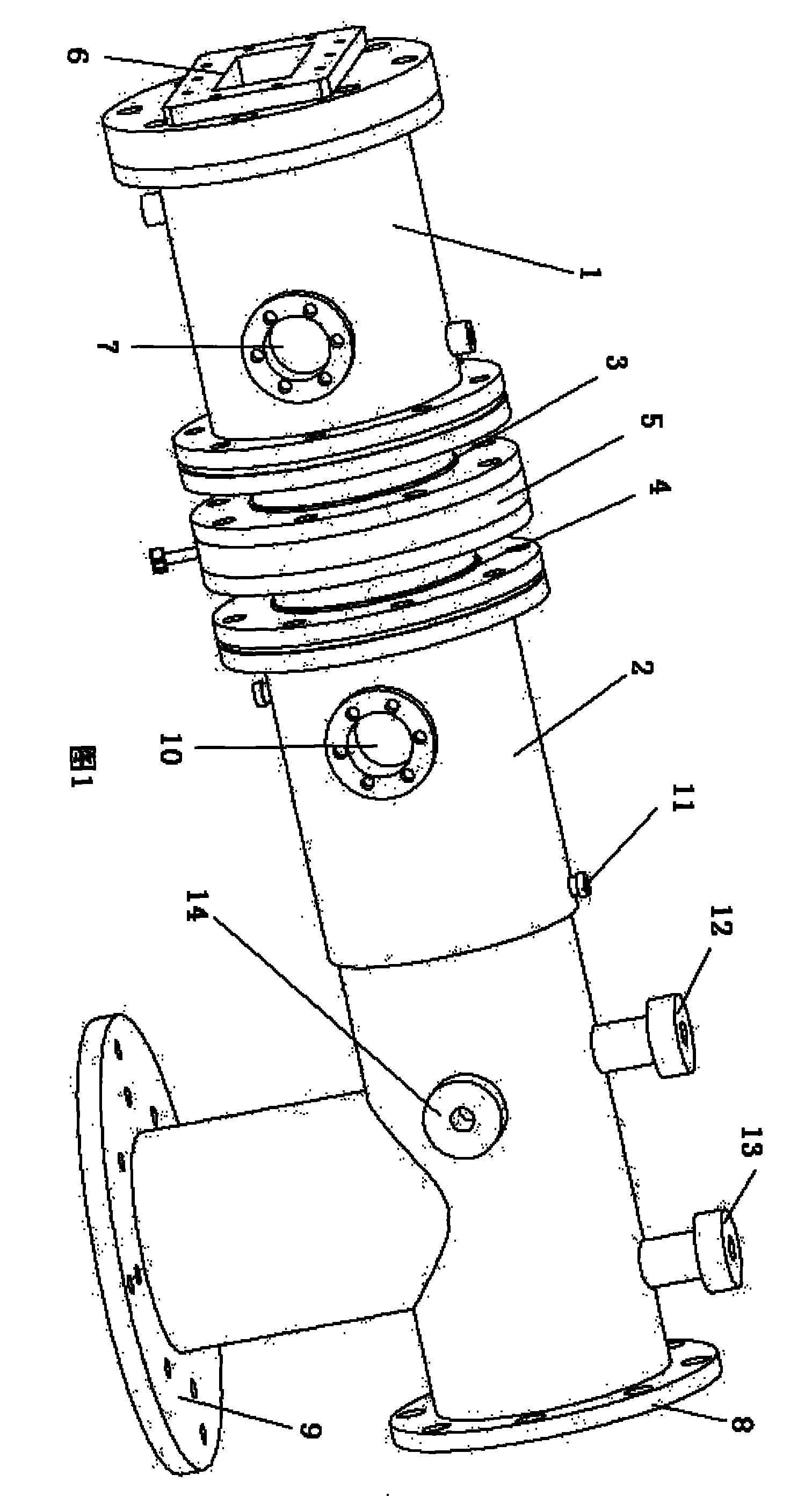
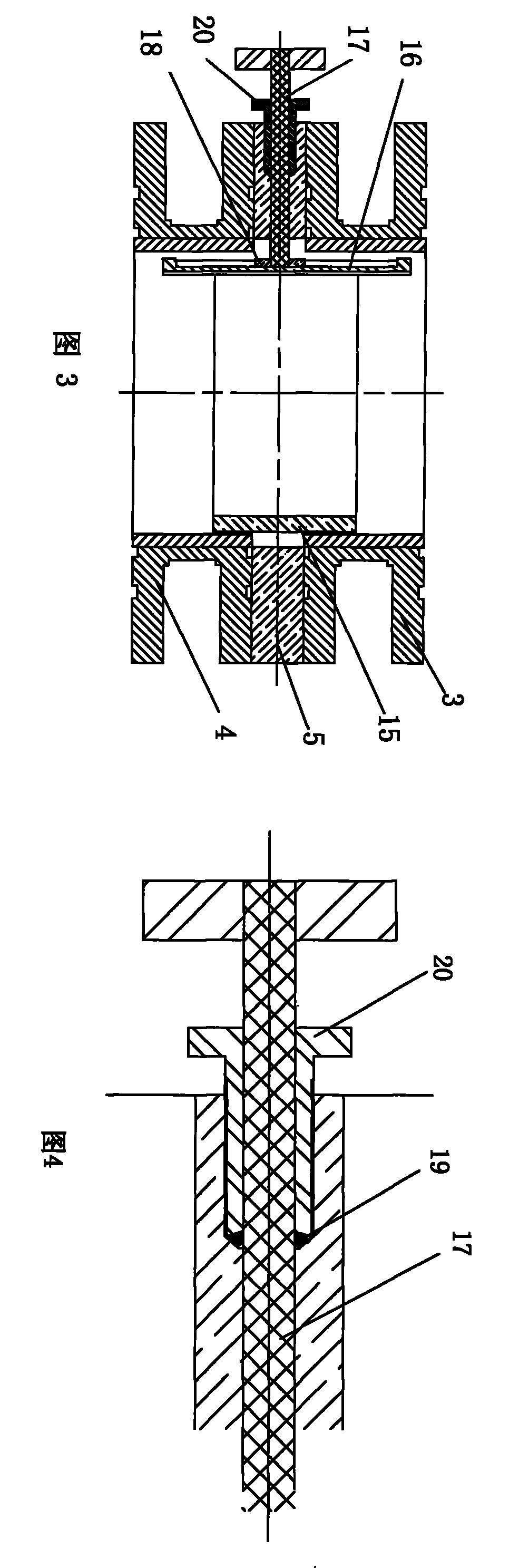
[0019] Referring to FIG. 1 , a particle source chamber structure of an ECR plasma sputtering device mainly includes: a left vacuum chamber 1 , a right vacuum chamber 2 and two target chambers, namely left and right target chambers 3 and 4 . The left vacuum chamber 1, the left target chamber 3, the right target chamber 4, and the right vacuum chamber 2 are sequentially connected by flanges, and a gasket 5 is arranged between the left and right target chambers 3 and 4, and the material of the gasket 5 is polyester Tetrafluoroethylene. Different targets are respectively placed in the left and right target cavities 3 and 4, and the targets are ring-shaped.

[0020] The entrance of the left vacuum chamber 1 is provided with a quartz window 6, and a first observation window 7 is arranged radially close to the left target chamber 1; the axial outlet of the right vacuum chamber 2 is provided with a retainer flange 8 connected to the substrate, radially The outlet is provided with a m...


PUM


Abstract

The invention relates to an electron cyclotron resonance (ECR) plasma sputtering device and discloses a cavity structure of the ECR plasma sputtering device, which is capable of conveniently changing particle sources. The cavity structure comprises a left vacuum cavity (1), a right vacuum cavity (2) and at least two target cavities (3, 4); wherein, the target cavities (3, 4) are connected between the left vacuum cavity and the right vacuum cavity (1, 2) and are internally provided with targets. The cavity structure is characterized in that a washer (5) is arranged between adjacent target cavities (3, 4) and is provided with a driving rod (17) in the radial direction; the inner end of the driving rod (17) is provided with a gear (18); a sliding check ring (15) is arranged in the adjacent target cavities (3, 4); the outer wall of the check ring (15) is inlaid with a rack (16) in the axial direction; the rack (16) is meshed with the gear (18) and a dynamic sealing equipment is arranged between the washer (5) and the driving rod (17).

Description

technical field [0001] The invention relates to an electron cyclotron resonance (ECR) plasma sputtering device, in particular to a cavity structure of the ECR plasma sputtering device capable of conveniently switching ion sources. Background technique [0002] With the in-depth development of nanoscience and nanoengineering technology, it has become possible to perform nanofabrication on solid surfaces (atomic doping, molecular assembly, nanostructure compounding, and surface nanopeak morphology arrangement) on different scales. Micro-nano devices and systems with different nano-functions provide a broad space and unlimited opportunities. ECR plasma sputtering processing technology has attracted the attention and research of many scholars due to its excellent performance in micro-nano structure composite, material surface processing and modification, and element doping. ECR plasma processing technology originated from electron cyclotron resonance technology in the research ...

Claims


Application Information

Patent Timeline
Patent Type & Authority Patents(China)
IPC IPC(8): C23C14/34C23C14/56
Inventor 刁东风王凯
Owner XI AN JIAOTONG UNIV
Why Eureka
Try Eureka