Automatic feeding assembling and transmitting device for electronic elements

A conveying device and automatic feeding technology, applied in the direction of electrical components, electrical components, etc., can solve problems such as low efficiency, workers are susceptible to corrosion and pollution, and achieve the effect of improving production efficiency, saving manpower and material resources, and realizing automatic operation

Inactive Publication Date: 2012-07-25
深圳市中科创安科技有限公司
3 Cites 26 Cited by

AI-Extracted Technical Summary

Problems solved by technology

In the whole process, workers are required to operate at each station. Usually, each station sets the number of people working in parallel according to the working time; but on the one hand, the efficiency of this manual processing process...

Method used

Concrete embodiment of the present invention is shown in conjunction with Fig. 1, and the gluing process module of its mechanical system can be set as two sets in parallel, the automatic feeding module 110 that is parallel setting, automatic gluing module 120, shared positioning transmission module 130 , the clamping and picking module 140, and the conveying and transferring module 150 are only designed for the control unit to realize the clamping and transferring of two electronic components to be processed, so that multiple automatic gluing modules can be used to perform the gluing process at the same time, in parallel The setting method makes full use of the space of the workstation and improves the work efficiency by at least one time.
Described grid base and slide block 105 are driven by synchronous belt, and this synchronous belt is arranged between pulley 108 and the drive shaft of first drive motor 114, and is provided with a motor on this first drive motor 114 The protective cover 116 is shown in FIG. 2 . The grid base is controlled to align the selected material tube with the inlet of the feeding trough 113 , so that the electronic components in the multiple material tubes can be fed into the feeding trough 113 correspondingly in turn. The feeding trough 113 can be realized by the cooperation of two parts, and has a curved downward track, the upper end is slightly vertically arranged, and the lower end is arranged nearly horizontally; in order to facilitate the downward movement of the electronic components, a roller brush or Air blowing head to increase the thrust to facilitate the smooth completion of the feeding process. In this way, all the feeding tubes can be fed sequentially.
Simultaneously according to technique needs, can also combine a plurality of crystals simultaneously, device of the present invention can finish the parallel gluing process of 1-4 sheet electronic element simultaneously by the expansion of space; Simultaneously, automatic feeding module 110 and automatic gluing ( dispensing) modules 120 are fixed together, and the clamping and picking module 140 is fixedly connected with the delivery transfer module 150. At the same time, in order to ensure the saving of structure and space, thereby reducing the cost of equipment, the automatic feeding module 110 The combination of modules formed by the automatic gluing module 120 and the combined processing direction formed by the clamping pick-and-place module 140 and the conveying transfer module 150 are distributed at 90°. This slightly vertical arrangement can facilitate the automatic feeding and gluing process. Two or more electronic components in parallel are processed together, and after the processing is completed, the parallel multiple electronic components are clamped, transported and transferred in the direction of their arrangement. Each of the above modules is fixed on the frame 160, and the frame 160 is fixed on the corresponding assembly line through other platforms or support structures, so that the present invention completes the corresponding process.
Simultaneously, by automatic feeding module and corresponding control unit control, once can install the feed pipe of 1~20 pipe electronic components, and can automatically identify the state of lack of material, complete the automatic feeding of 1~20 pipe materials in sequence, Improved processing efficiency. When setting multiple automatic feeding and automatic gluing in parallel, and using a common positioning transfer module, the two-station electronic component gluing and conveying pr...

Abstract

The invention discloses an automatic feeding assembling and transmitting device for electronic elements, which comprises automatic feeding modules, an automatic gluing module, a positioning and transmitting module and a clamping and taking-placing module a well as a transmitting and transferring module, wherein each automatic feeding module is provided with at least one feeding slot which is used for arranging and placing electronic elements to be machined, the automatic gluing module is provided with corresponding glue storage barrels and gluing heads communicated with the glue storage barrels, the gluing heads is arranged at outlets of the feeding slots, the positioning and transmitting module comprises discharging slots arranged below the gluing heads, and positioning and transmitting structures for pushing the discharging slots to move, and the clamping and taking-placing module comprises clamping and grabbing parts for clamping the electronic elements in the discharging slots by driving. According to the automatic feeding assembling and transmitting device for the electronic elements, operation of feeding, dispensing and clamping components can be realized on the same platform, so that automatic operation can be realized.

Application Domain

Technology Topic

Image

  • Automatic feeding assembling and transmitting device for electronic elements
  • Automatic feeding assembling and transmitting device for electronic elements
  • Automatic feeding assembling and transmitting device for electronic elements

Examples

  • Experimental program(1)

Example Embodiment

[0032] The preferred embodiments of the present invention will be described in detail below.
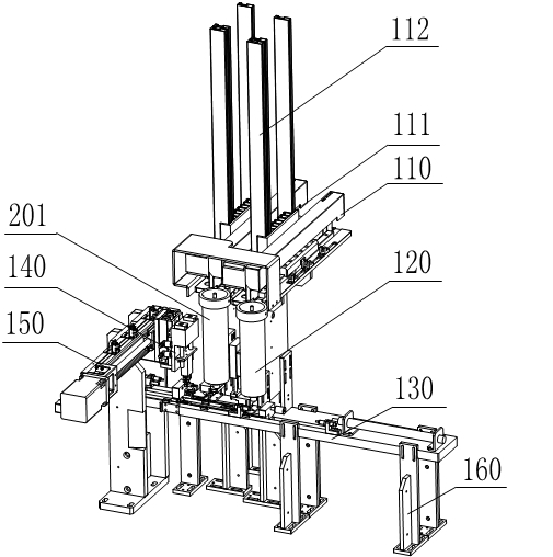
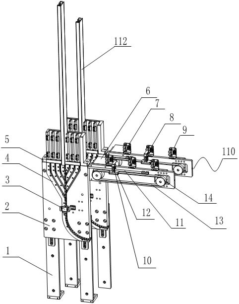
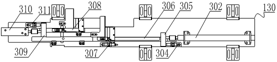
[0033] The electronic component automatic feeding assembly and transportation device of the present invention is mainly aimed at the electronic components that need to be glued and installed, mainly power components; the glue-dispensing installation includes the installation for fixing the glue or heat conduction. The device of the present invention mainly includes The automatic feeding module 110, the automatic gluing module 120, the positioning and transferring module 130, the clamping and picking module 140, and the conveying and transferring module 150, such as figure 1 Shown.
[0034] The above modules are fixed on the platform or bracket according to the work coordination process, figure 1 The shown in the figure only shows the positional relationship, and does not show the platform or support. In actual production, the device of the present invention can be set on various platforms or supports; among them, the automatic feeding module 110 is mainly used to realize the electronic components The automatic feeding function is usually provided with at least one slot 111 for placing electronic components, preferably multiple slots, and each slot can be inserted with a material tube 112 arranged in sequence to set the electronic components to be installed, for example The material tube where the power transistor is placed, adopts the corresponding material tube and slot according to the different electronic components to be processed; at the same time, at least one sensor must be set to detect the number of electronic components in the feeding trough, and can make a prompt Or call the police.
[0035] Under the action of the automatic feeding and detection system of the automatic feeding module, the device of the present invention can be provided with multiple slots arranged in parallel at a time, such as figure 2 As shown, 1 to 20 material tubes are placed in parallel, and the slots together with the material tubes can be moved in a controlled manner, so that the corresponding material tubes and slots correspond to the feeding trough 113, which is arranged in the automatic feeding module On the body of 110, a plurality of electronic components are sequentially arranged along the feeding trough 113, so that the electronic components in the feeding trough 113 can maintain the continuity of processing, so as to load and unload the material tube in the slot. The feeding trough 113 can be arranged in a curved arc shape, the entrance is slightly vertical, and the exit is close to the horizontal arrangement; the original packaged electronic components are usually set in the material tube, pre-assembled to form a strip of material tubes, After being assembled into the device of the present invention, the electronic components will slip and fall in the feeding trough of the automatic feeding module, and the electronic components will be automatically loaded in sequence under the push of gravity or additional power such as airflow or rolling brush. In order to realize the feeding, a switch component that controls opening and closing can also be provided at the bottom end of the feeding trough of the automatic feeding module 110, and the electronic components are automatically fed and replenished when the electronic components are about to be used up.
[0036] The automatic glue application module 120 realizes automatic positioning and glue application functions, such as applying heat dissipation paste, bonding glue, etc., on the device of the present invention, the automatic glue application module and the automatic feeding module are fixedly connected on a whole Yes, for example, it can be fixed by a platform or a support structure.
[0037] The positioning transfer module 130 of the present invention realizes the function of the positioning transfer module: the electronic components that have completed the gluing process are transported to the clamping module, waiting to be transferred to the next station.
[0038] The clamping and picking module 140 and the transfer and transfer module 150 of the present invention realize the functions of clamping and picking and conveying: the picking and placing of electronic components is realized by the clamping and picking module, and the electronic components are applied in the present invention by the conveying and transferring module. After the glue process is completed, it is transferred to the next station of the production line; in the device of the present invention, the clamping and picking module 140 and the transfer conveying module 150 are also fixedly connected together, and can be connected to each other through a bracket or a platform. Fix the position.
[0039] The device of the present invention can liberate labor, improve production efficiency, and improve product assembly quality by setting automatic processing modules.
[0040] Specific embodiments of the present invention combine figure 1 As shown, the gluing process modules of the mechanical system can be set in parallel as two sets, namely, the automatic feeding module 110, the automatic gluing module 120, the common positioning and conveying module 130, the clamping and picking module 140, and the conveying and transferring module. Module 150, only the control unit is designed to realize the clamping and transfer of two pieces of electronic components to be processed. In this way, multiple automatic gluing modules can be used to carry out the gluing process at the same time. The parallel setting mode makes full use of the space of the workstation and improves At least double the work efficiency.
[0041] At the same time, according to process requirements, multiple crystals can be combined at the same time. Through the expansion of space, the device of the present invention can simultaneously complete the parallel gluing process of 1-4 electronic components; at the same time, the automatic feeding module 110 and automatic gluing (dispensing) The modules 120 are fixedly connected together, and the holding and placing module 140 and the conveying and transferring module 150 are fixedly connected together. At the same time, in order to ensure the saving of structure and space, thereby reducing the equipment cost, the automatic feeding module 110 and the automatic coating The module combination formed by the glue module 120 and the combined processing direction formed by the clamping, picking and placing module 140 and the conveying transfer module 150 are distributed at 90°. This slightly vertical arrangement can facilitate the parallel two processes of automatic feeding and gluing. The above electronic components are processed together, and after the processing is completed, a plurality of parallel electronic components are clamped and transported in the arrangement direction. All the above modules are fixed on the rack 160, and the rack 160 is fixed on the corresponding production line through other platforms or support structures, so that the present invention completes the corresponding process.
[0042] Such as figure 2 Shown is the realization structure diagram of the automatic feeding module 110 and the automatic gluing module 120 of the electronic component automatic feeding assembly and transportation device of the present invention. Its specific functions include: the electronic components to be processed are original electronic components, placed in a tubular material In the tube 112, the material tube 112 is inserted into a grid base with a plurality of parallel slots 111. The device of the present invention can be inserted into the 20-tube material tube 112 at a time; the grid base is connected to the rail 106 through the slider 105, which is connected to the grid base and can be reciprocated on the support 115 under the drive of the first drive motor 114 Movement, the support 115 is fixedly connected with the automatic glue application module 120. The first driving motor 114 adopts a stepping motor, and drives the grid base and the slider 105 through a timing belt under the control of a control driver.
[0043] The grid base and the slider 105 are driven by a timing belt, which is arranged between the pulley 108 and the drive shaft of the first drive motor 114, and a motor protection cover 116 is provided on the first drive motor 114 ,Such as figure 2 Shown. The grid base is controlled to realize the alignment of the selected material tube with the inlet of the feeding trough 113, so that the electronic components in the multiple feeding tubes can be sent into the feeding trough 113 correspondingly in sequence. The feeding trough 113 can be realized by the cooperation of two parts, and has a curved downward track, the upper end is slightly vertical, and the lower end is close to the horizontal setting; in order to facilitate the downward movement of the electronic components therein, a rolling brush or Blow head to increase thrust and facilitate the smooth completion of the feeding process. In this way, all the material pipes can be fed sequentially.
[0044] The key point of the device of the present invention is that a photoelectric sensor 117 with lack of material detection is provided in the feeding trough 113. Preferably, the photoelectric sensor 117 can be arranged near the entrance of the feeding trough 113. When it is detected that the number of electronic components in the feeding trough 113 is insufficient (the photoelectric sensor does not detect the blocking signal of the electronic components, the control unit determines and issues an instruction), it can automatically issue a drive instruction to the first drive motor 114 to drive the grid base to proceed. For translation, the material tubes can be translated sequentially until the electronic components in the next material tube 112 are fed, so that there are enough electronic components in the feeding trough 113. If all the slots in the grid base have been docked to the feeding trough in turn, and the number of electronic components in the feeding trough 113 is still not satisfied, the control unit can send an alarm signal, such as flashing warning lights or sounding warnings flute.
[0045] Such as figure 1 with figure 2 As shown, a plurality of glue storage cylinders 201 are arranged at the bottom end of the feeding trough 113. In the embodiment shown in the figure, the glue storage cylinders 201 are arranged in two corresponding to the automatic feeding modules arranged in parallel for Store glue or other paste-like substances, and set a glue head 203 below the glue storage cylinder 201, the glue head 203 is fixed on the front support of the double-rod drive cylinder 202, the glue storage cylinder 201 and the glue head 203 They are connected by a hose 211. When the electronic component reaches a limited position just below the glue head 203 along the feeding tank 113 under the action of the automatic feeding module 110, the double-rod cylinder 202 goes down to drive the glue in the hose 211 down , So as to complete the glue (dispensing) process on the electronic components. The functions of the two sets of automatic feeding module and automatic gluing module set in parallel are the same, so that parallel processing can be realized.
[0046] Such as Figure 3a with Figure 3b As shown, it is a diagram of a specific implementation scheme of the positioning transmission module 130 of the present invention, and its specific structure and functions are described as follows:
[0047] The positioning and conveying module 130 is provided below the glue application head 203, and the positioning and transmission module 130 is provided with two discharge slots 131 and 132 corresponding to the number of the glue application heads, respectively corresponding to the automatic feeding modules arranged in parallel. The two feeding trough outlets in 110; the conveying movement direction of the positioning and conveying module 130 is set perpendicular to the plane where the feeding trough is located, thereby facilitating the spatial arrangement and setting of the entire equipment. The positioning transmission module 130 is provided with two positioning transmission structures that are oppositely arranged, including a first transfer sliding block 308 and a first cylinder top block 309 fixedly connected thereto, a first push-pull cylinder 310 and a first oil The pressure buffer 311 is connected, and the first transfer slider 308 is pushed by the first push-pull cylinder 310 to transfer one of the electronic components from the corresponding position of the discharge trough 132 to the clamping station. The position of the clamping station is changed from the first The hydraulic buffer 311 ensures that the first transfer slider 308 slides in the slotted slide of the base 302; similarly, another electronic component is in the second push-pull cylinder 302, the second cylinder top block 305, and the second transfer slider 306, The transmission of the second oil pressure buffer 304 and the third oil pressure buffer 307 is sent down to the corresponding clamping station. Combining the shapes of different electronic components, the shape of the feeding trough and the shape of the gripping part of the present invention can be changed according to actual needs.
[0048] Such as Figure 4 As shown, it is a schematic diagram of a specific technical solution of the clamping and picking module 140 and the conveying and transferring module 150 of the present invention:
[0049] The clamping and picking module 140 is composed of a downward cylinder 401, a buffer rail 402, a cylinder base 403, a parallel clamping cylinder 404, and a clamping member 405. The buffer rail 402 is installed on the downward cylinder 401, and the parallel clamping cylinder 404 passes through the cylinder base. The 403 is installed on the buffer guide 402, and the buffer guide 402 and the screw base baffle are buffered by a spring. The parallel clamping cylinder 404 controls the opening and closing of the clamping member 405. When the system determines that the electronic component reaches the lower position of the clamping and picking module 140, the parallel clamping cylinder 404 pushes the clamping member 405 to open, and the downward clamping cylinder 401 drives the push rod to extend through the buffer guide 402 and the cylinder base 403. The parallel clamping cylinder 404 is sent to the clamping target position, and then the parallel clamping cylinder 404 is driven to control the clamping member 405 to contract and clamp the corresponding electronic components. The downward cylinder 401 is retracted by a push rod to complete clamping of the electronic components The crystal process.
[0050] The conveying and transferring module 150 is composed of a frame 501, a second driving motor 502, a coupling 503, a lead screw 504, a sliding block 507, and three photoelectric proximity switches 505, 506, 508; the clamping and picking module 140 That is, it is fixed on the slider 507. Under the action of the second drive motor 502, the slider 507 together with the clamping and picking module 140 reciprocate on the screw 504 to complete the electronic components from one station to the next. The transfer of stations; the photoelectric proximity switch 506 identifies the target position of the transport, the photoelectric proximity switch 505 identifies the limit position of the transport, the photoelectric proximity switch 508 identifies the initial position of the transport, and the corresponding photoelectric proximity switch is set on the slider 507 The blocking protrusion of the gap.
[0051] It should be noted that the automatic feeding module 110 in the device of the present invention can be used such as Figure 5 The alternative solution shown consists of a frame 1, a curved track 2, a photoelectric sensor 3, a curved track baffle 4, a grid material base 5, a drive motor 6, a photoelectric sensor switch 7, 8, 9 and a trigger block 10 , The latch rod 11, the fixed seat 12, the timing belt 13, and the timing belt wheel 14. The curved track baffle 4 is provided with a plurality of curved feeding grooves, specifically 20 can be set, corresponding to the grid material base 5. There are multiple slots for inserting 20 electronic components in the material tube 112. Each material tube corresponds to the entrance of a feeding trough. All feeding troughs have a common channel end. A slot is selected by the advance and retreat of the latch lever 11 Open. In this way, the curved track baffle 4 and the grid material base 5 are fixedly connected, and the grid material base 5 does not need to be moved. The discharge port of the material pipe can be opened in turn by the expansion and contraction of the latch rod 11 to control the downward movement of the electronic components. The feeding trough. The latch rod 11 is fixedly connected to the fixed seat 12 and the timing belt 13, and the timing belt wheel 14 is driven to rotate by the driving motor 6, thereby driving the latch rod 11 to move, thereby completing the above-mentioned cutting action.
[0052] Similarly, a lack of photoelectric sensor is installed in the feeding trough on the curved track plate to sense whether there is a lack of material. The photoelectric sensor can be installed in the common pipe section of the feed troughs so as to reduce the number of photoelectric sensors used; , A plurality of photoelectric sensors for positioning are provided on the path passed by the timing belt, such as Figure 5 As shown, the photoelectric sensor switches 7 and 9 are used to control the limit protection position of the drive motor 6 and no longer move outwards, while the photoelectric sensor switch 8 corresponds to the position of the vertical unloading channel in the curved track for use The fixed seat 12 is provided with a protrusion for passing through the photoelectric sensor switch 7-9.
[0053] For the clamping mode of the parallel clamping cylinder 404 in the clamping and picking module 140 of the present invention, the present invention is as Image 6 The alternative clamping solution shown is to realize the opening and closing of the gripping parts through a hinged shear structure. The system consists of a cylinder base 403, a linear cylinder 612, a driving link 613, a first driven link 614, and a second driven link 615. , The third driven connecting rod 616, the adaptive clip 617, wherein the cylinder base 403 is installed on the buffer rail, the linear cylinder 612 is fixed on the cylinder base 403, and one end of the driving connecting rod 613 arranged in parallel can be driven and connected. Moving up and down, the other end of the driving link 613 is hinged to the first driven link 614, the other end of the first driven link 614 is hinged to the third driven link 616, and the other end of the third driven link 616 One end is provided with the self-adaptive clamping piece 617 to clamp the electronic component 101 to be clamped from both sides. A hinge point is provided in the middle of the third driven link 616 for hinged connection with one end of the second driven link 615, and the other end of the second driven link 615 is hinged on the cylinder base 403 fixed structure. In order to realize the working distance of the adaptive clamping pieces 617, the third driven link 616 is provided with a certain degree of curvature, so as to ensure that the distance between the adaptive clamping pieces meets the clamping work of electronic components.
[0054] The invention is like Image 6 The clamping and picking module shown is moved through the telescopic movement of the linear cylinder 612, which can be driven by a driving link 613, a first driven link 614, a second driven link 615 and a third driven link 616 The movement of the four-bar mechanism finally realizes the opening and closing clamping action of the adaptive clip 617, so that the electronic components can be clamped and released. The self-adaptive clamping piece 617 is arranged in a relative orientation, and can have certain elasticity relative to its fixed bottom, which can ensure that the electronic component is actively self-adaptively clamped in the case of an electronic component size error.
[0055] Through the combination of the above-mentioned modules, the present invention forms a pair of electronic components for automatic feeding, gluing and clamping and conveying, especially for power devices that need glue, through the automatic feeding module, the automatic gluing module, and positioning and conveying The coordination function of the module, the clamping and picking module, and the conveying and transferring module can automatically complete the automatic feeding, automatic dispensing (gluing), and conveying and transferring functions of related electronic components, saving a lot of manpower.
[0056] At the same time, through the automatic feeding module and the corresponding control unit control, 1-20 tubes of electronic components can be installed at a time, and the lack of material can be automatically recognized, and the automatic feeding of 1-20 tubes can be completed in sequence, which improves the processing effectiveness. When multiple automatic feeding and automatic gluing are installed in parallel, and a common positioning and conveying module is adopted, the gluing and conveying process of electronic components at two stations can be completed in parallel at the same time, which further improves work efficiency.
[0057] The electronic component automatic feeding, gluing and clamping and conveying device of the present invention can automatically complete the picking and placing process of electronic components through the automatic clamping and picking module 140. At the same time, the clamping part has a buffer structure to protect the parallel clamping cylinder, which can be more The gripping process of the electronic components is carried out efficiently; then, the automatic transfer process of the electronic components from the gluing station to the next station can be realized through the conveying and transferring module 150.
[0058] The equipment of the invention can automatically realize the glue coating process, thereby reducing the need for labor and realizing an efficient industrial automation process. The present invention completely integrates the process flow of feeding, gluing, picking and placing, positioning, etc. in an automatic device, and can complete the parallel process flow of more than two electronic components at the same time, changing the current requirement of human operation for each station Disadvantages, save a lot of labor costs, and improve the consistency and reliability of the product.
[0059] The invention has undergone experiments and relevant operation statistics, and has been verified by internal physical operations, which proves the effectiveness and correctness of the device of the invention, and can quickly complete the feeding, gluing, picking and placing of electronic components in accordance with the requirements of the beat and timing. The transfer and other technological processes have fulfilled the requirements of high efficiency and accuracy.
[0060] It should be understood that those of ordinary skill in the art can make improvements or changes based on the above description, and all these improvements and changes should fall within the protection scope of the appended claims of the present invention.

PUM

no PUM

Description & Claims & Application Information

We can also present the details of the Description, Claims and Application information to help users get a comprehensive understanding of the technical details of the patent, such as background art, summary of invention, brief description of drawings, description of embodiments, and other original content. On the other hand, users can also determine the specific scope of protection of the technology through the list of claims; as well as understand the changes in the life cycle of the technology with the presentation of the patent timeline. Login to view more.

Similar technology patents

Custom operation method and device for terminal

InactiveCN103530133ATimed automatic operationAutomate operationSpecific program execution arrangementsReal-time computingSystem level
Owner:GUANGDONG OPPO MOBILE TELECOMM CORP LTD

Automatic cleaning system capable of deeply cleaning smoke box

Owner:云南众诚士德柔性自动化设备有限公司

Classification and recommendation of technical efficacy words

  • Automate operation
  • Save manpower and material resources

Mobile radioactive liquid waste treatment equipment

Owner:RES INST OF PHYSICAL & CHEM ENG OF NUCLEAR IND +3

Lifting rope angle measurer for crane

InactiveCN1436715ASuitable for operation automationAutomate operationUsing electrical meansCranesSUSPENDING VEHICLEEngineering
Owner:INST OF AUTOMATION CHINESE ACAD OF SCI
Why Eureka
Try Eureka