
Automatic switching device for optical filter of camera head

A technology of automatic switching and camera, applied in the direction of optics, instrument, camera body, etc., can solve the problems of low reliability, low price, incomplete work and misalignment, etc., and achieve strong versatility, simple use and control, The effect of high reliability

Inactive Publication Date: 2009-08-19
惠州龙德科技股份有限公司
View PDF3 Cites 22 Cited by
  • Summary
  • Abstract
  • Description
  • Claims
  • Application Information

AI Technical Summary

Problems solved by technology

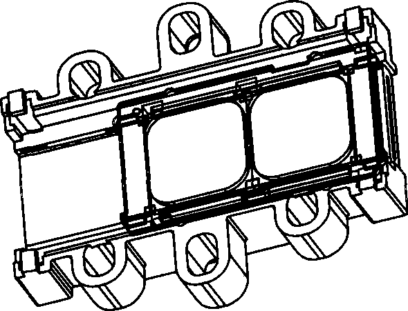
This kind of magnetic switching device mainly uses electromagnetic pull to drive the movement and switching of the filter. Its price is low, but its reliability is not high, and it is easy to cause problems such as improper work and misalignment. It can only be used for low requirements. low-end security products

Method used


Image

  • Automatic switching device for optical filter of camera head
  • Automatic switching device for optical filter of camera head
  • Automatic switching device for optical filter of camera head

Examples


Embodiment Construction

[0015] In order to facilitate the understanding of those skilled in the art, the structural principle of the present invention will be further described in detail below in conjunction with specific embodiments and accompanying drawings:

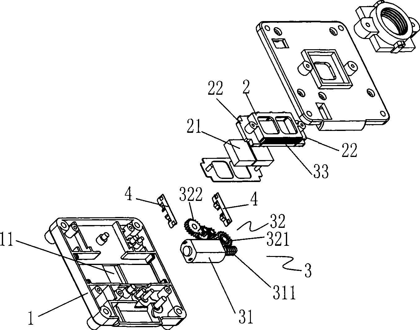
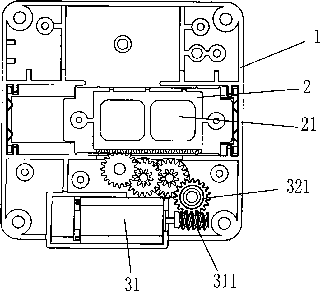
[0016] as attached Figure 2-5 As shown, the camera filter automatic switching device disclosed in this scheme adopts an existing micro-motor with small size and stable performance as power, and uses a gear with stable transmission as a transmission component, which is small in size and high in stability.

[0017] The device includes a box body 1 installed at the front end of the camera, an optical filter 21 and a driving assembly 3 installed inside the box body 1 . Wherein, the casing 1 is provided with a lens hole 11, and the lens hole 11 is used for the lens of the camera, and the external light enters into the camera through the lens hole 11. A mounting frame 2 is installed around the lens hole 11 inside the cabinet 1, the mounting frame...


PUM


Abstract

A camera filter automatic switching device comprises a box installed on a camera; the box is provided with a lens opening which is corresponding to the lens of the camera; an installing frame which can slide directionally is installed on the lens opening; two parallel filters are fixed on the installing frame; a drive component which drives the installing frame to move is fixed in the box; wherein, the drive component comprises a micro-motor and an reduction gear set which rotate synchronously with the output shaft of the micro-motor; and a rack which is meshed with the reduction gear set is installed on a fixing frame. Simultaneously, the two ends of the box on which the installing frames are installed are provided with buffer components which prevent the installing frames from being rigidly collided with the inner wall of the box when sliding to a limit position. The invention has the advantages of compact structure, small size, high reliability, easy installation, simple use and control, good filtering effect, strong universality, and the like. With the ordinary micro-motor and a precision drive mechanism, the camera filter automatic switching device is not only provided with the advantages of the existing products, but also avoids the original shortcomings, thereby being more capable of meeting the market demand.

Description

technical field [0001] The invention relates to a device used in a camera, in particular to an automatic switching device for a camera optical filter. Background technique [0002] Security cameras play an important role in combating crimes, and security cameras are installed in the streets and alleys of many cities. Since the security camera needs to take pictures 24 hours a day, it must be able to automatically adapt to both day and night light environments. At present, this function is generally realized by installing a blue filter and a white filter on the front end of the camera, switching to a blue filter during the day and switching to a white filter at night, and switching between the two filters It needs to be done by switching device. [0003] Now there is a switching device on the market that uses electromagnetic suction to drive the filter to switch, such as the attached figure 1 shown. This kind of magnetic switching device mainly uses electromagnetic pull t...

Claims


Application Information

Patent Timeline
Patent Type & Authority Applications(China)
IPC IPC(8): G03B17/14
Inventor 刘宏伟方路星卢致辉
Owner 惠州龙德科技股份有限公司
Learn More