Current balance power supply circuit of multi-group light-emitting diode

A technology of light-emitting diodes and power supply circuits, which is applied to the layout of electric lamp circuits, semiconductor devices of light-emitting elements, and circuit layout. The effect of low loss and the same luminous brightness

Active Publication Date: 2009-08-19
DELTA ELECTRONICS INC
View PDF1 Cites 34 Cited by
  • Summary
  • Abstract
  • Description
  • Claims
  • Application Information

AI Technical Summary

Problems solved by technology

[0005] However, the traditional multi-group LED current balance power supply circuit uses linear voltage regulators and current mirrors, resulting in large circuit power loss and low circuit operation efficiency. Relatively more components are used and the circuit is more complicated.

Method used


Image

  • Current balance power supply circuit of multi-group light-emitting diode
  • Current balance power supply circuit of multi-group light-emitting diode
  • Current balance power supply circuit of multi-group light-emitting diode

Examples


Embodiment Construction

[0058] Some typical embodiments embodying the features and advantages of the present invention will be described in detail in the description in the following paragraphs. It should be understood that the present invention is capable of various changes in different aspects without departing from the scope of the present invention, and that the description and drawings therein are illustrative in nature and not intended to limit the present invention.

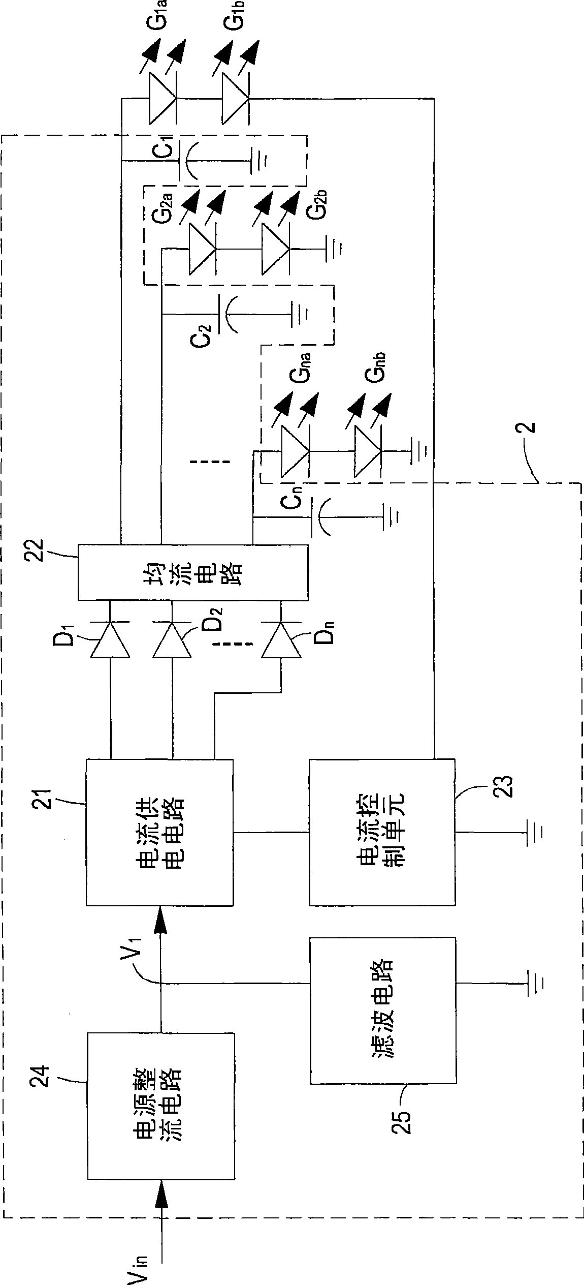
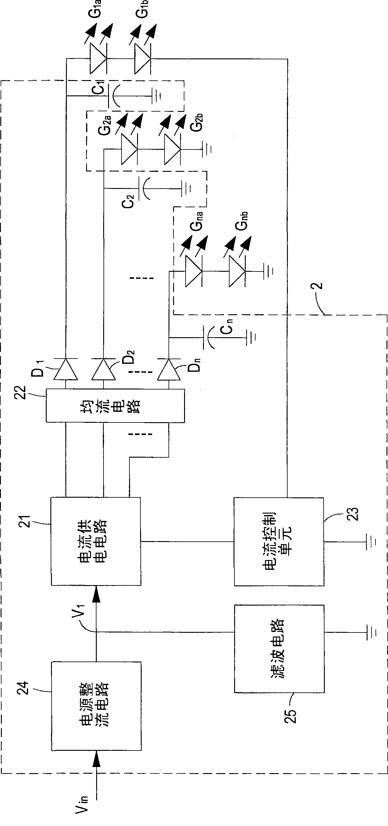
[0059] The current balanced power supply circuit for multiple groups of LEDs of the present invention is used for multiple groups of LEDs, and each group of LEDs can have multiple LEDs. The following will illustrate by taking each group of LEDs with two LEDs as an example. . see Figure 2A , which is a schematic circuit block diagram of a current balance power supply circuit for multiple sets of LEDs in a preferred embodiment of the present invention. Such as Figure 2A As shown, the current balance power supply circuit 2 of m...


PUM


Abstract

The invention relates to a current balance power supply circuit of a multi-group LBD for driving the multi-group LBD to has same luminosity. The current balance power supply circuit at least contains: a current power supply circuit for receiving the electrical power source and converting into a current with a special current size for providing to the multi-group LBD; a flow equalization circuit connected with the current power supply circuit and multi-group LBD which contains at least a coupling inductor for balancing the multi-group LBD current size; and a current control unit connected withthe current power supply circuit and at least one group LBD of the multi-group LBD for detecting current size of the multi-group LBD and controlling the output current of the current power circuit. The current balance power supply circuit can make each group LBD current balance and has same luminosity, low circuit power consumption, high operating efficiency, less element and low circuit complexity, and save cost greatly.

Description

technical field [0001] The invention relates to a power supply circuit, in particular to a current balanced power supply circuit for multiple groups of light emitting diodes. Background technique [0002] In recent years, due to breakthroughs in light emitting diode (Light Emitting Diode, LED) manufacturing technology, the luminous brightness and luminous efficiency of light emitting diodes have been greatly improved. Therefore, light emitting diodes have gradually replaced traditional lamps and become new lighting components, and are widely used in household lighting, for example. Devices, automotive lighting devices, hand-held lighting devices, LCD panel backlight, traffic signal lights, sign boards and other lighting applications. [0003] In the application of multiple light-emitting diodes, since the characteristics of each light-emitting diode are different from each other, the magnitude of the current flowing through each light-emitting diode is not the same, which no...

Claims


Application Information

Patent Timeline
Patent Type & Authority Applications(China)
IPC IPC(8): H05B37/00H05B37/02G05F1/46F21V23/00F21Y101/02F21Y115/10H05B44/00
CPCY02B20/347Y02B20/30
Inventor 郑清奇颜上进黄仲才李柏毅
Owner DELTA ELECTRONICS INC
Why Eureka
Try Eureka