Switch constant-current source circuit without feedback on load end

A technology of constant current source and circuit, applied in the direction of lamp circuit layout, light source, electric light source, etc., can solve the problems of different brightness, constant current failure, sensitive instruments and equipment, etc., to solve high-frequency flicker and EMI problems Effect

Inactive Publication Date: 2009-08-19
SOUTH CHINA UNIV OF TECH
View PDF0 Cites 22 Cited by
  • Summary
  • Abstract
  • Description
  • Claims
  • Application Information

AI Technical Summary

Problems solved by technology

Although most people can't tell whether the light source is flickering because of the persistence of vision, they think that the light emitted by the LED is stable and continuous, but the equipment is extremely sensitive to this, which is reflected in the brightness of the light in the photos taken by the camera. , and the result of the video recorder is to see the lights flickering constantly
Furthermore, since the existing switching constant current PWM technology generally performs current feedback sampling directly at the load end, it is impossible to filter the output low-frequency rectangular wave, otherwise the constant current will fail
[0004] From the above, how to solve the EMI and high-frequency flicker problems caused by the existing PWM dimming technology has become a technical problem to be solved urgently by those skilled in the art.

Method used


Image

  • Switch constant-current source circuit without feedback on load end
  • Switch constant-current source circuit without feedback on load end
  • Switch constant-current source circuit without feedback on load end

Examples


Embodiment Construction

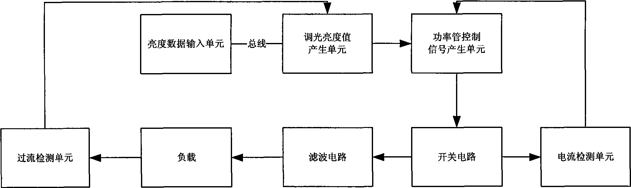
[0016] see image 3 The switch constant current source circuit without feedback at the load end of the present invention at least includes: a brightness data input unit, an overcurrent detection unit, a bus, a dimming brightness value generation unit, a power tube control signal generation unit, a switch circuit, a filter circuit, and current detection unit.

[0017] The brightness data input unit has a bus interface for inputting brightness data, wherein the brightness data can be DMX data conforming to the DMX512 protocol.

[0018] The over-current detection unit is connected to a load for detecting whether the load current reaches an over-current value, which may include an optocoupler connected to the load, and the load may be an LED or the like.

[0019] The bus can be an RS485 bus.

[0020] The dimming brightness value generation unit has a bus interface, is connected to the overcurrent detection unit, and is connected to the brightness data input unit through the bus,...


PUM


Abstract

The invention provides a switch constant flow source circuit with no-feedback load end which includes: a brightness data input unit; an over-current detecting unit connected with the load; a bus; an aiming brightness value generating unit for generating corresponding aiming brightness value according with the brightness data, aiming brightness initial value and the rated operating current preset by the load, a power pipe control signal generating unit for generating corresponding control signal according with the aiming brightness value; a switch circuit with a power pipe for closing and opening the power pipe to output a high frequency signal according with the power pipe control signal; a filtering circuit with DC signal for filtering the high frequency signal filter and forming a driving load; a current detecting unit that feedbacks the detected present load current value to the power pipe control signal generating unit for adjusting the generated power control signal to realize constant current, wherein, the aiming brightness initial value is generated by the time for raising the load current from 0 to the over-current value continuously which can solve problems of electromagnetic interference and high frequency spark.

Description

technical field [0001] The invention relates to a switch constant current source circuit, in particular to a switch constant current source circuit without feedback at the load end. Background technique [0002] No matter in the field of lighting, backlight or display panel, the driving circuit is an important part of LED products, and its technical maturity is gradually increasing with the expansion of the LED market. The driving circuit is mainly to provide a constant current for the LED to ensure the stability and uniformity of its luminous intensity. At present, the relatively mature technologies in LED constant current drive generally include linear constant current drive control technology and switching power supply constant current drive technology, both of which are step-down drives. Among them, the linear constant current drive control technology has a simple structure and low cost, but because the constant current drive is connected in series between the input and...

Claims


Application Information

Patent Timeline
Patent Type & Authority Applications(China)
IPC IPC(8): H05B37/02
CPCY02B20/42Y02B20/40
Inventor 王前李韬
Owner SOUTH CHINA UNIV OF TECH
Why Eureka
Try Eureka