Electronic equipment circuit system architecture and laser theater equipment

A circuit system and electronic equipment technology, applied in the direction of grounding circuit, electrical components, magnetic field/electric field shielding, etc., can solve the problems of large ground loop impedance, electromagnetic radiation interference of electronic equipment, etc., achieve good shielding effect, prevent EMI problems, reduce The effect of small impedance

Active Publication Date: 2019-07-02
QINGDAO HISENSE LASER DISPLAY CO LTD
View PDF7 Cites 0 Cited by
  • Summary
  • Abstract
  • Description
  • Claims
  • Application Information

AI Technical Summary

Problems solved by technology

[0006] The embodiment of the present invention provides an electronic equipment circuit system architecture and laser cinema equipment, which are used to solve the serious electromagnetic radiation interference caused by the large ground loop impedance between the electronic equipment and the circuit board inside the laser cinema equipment in the prior art. The problem

Method used


Image

  • Electronic equipment circuit system architecture and laser theater equipment
  • Electronic equipment circuit system architecture and laser theater equipment
  • Electronic equipment circuit system architecture and laser theater equipment

Examples


Embodiment 1

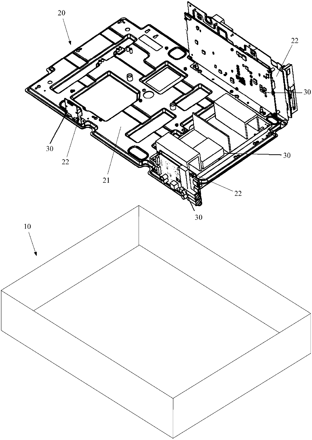
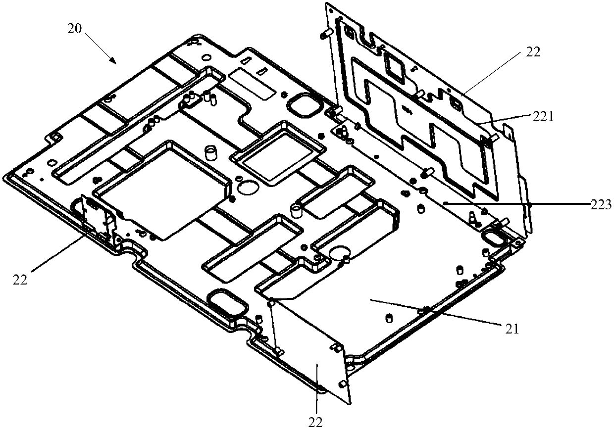
[0028] figure 2 It is a schematic structural diagram of an electronic device circuit system architecture according to an embodiment of the present invention. image 3 It is a schematic structural diagram of a ground plane in the circuit system architecture of an electronic device according to an embodiment of the present invention. Figure 4 It is a schematic diagram of the assembly of the ground plane board and the circuit board in the circuit system architecture of the electronic device according to the embodiment of the present invention.

[0029] see Figure 2 to Figure 4 , the circuit system architecture of the electronic equipment provided by the embodiment of the present invention includes: a ground plane board 20 and at least two circuit boards 30 installed in the housing 10 of the electronic equipment, the ground plane board 20 has a base plate 21 and a wall perpendicular to the base plate 21 The side plate 22, the at least two circuit boards 30 are installed on th...

Embodiment 2

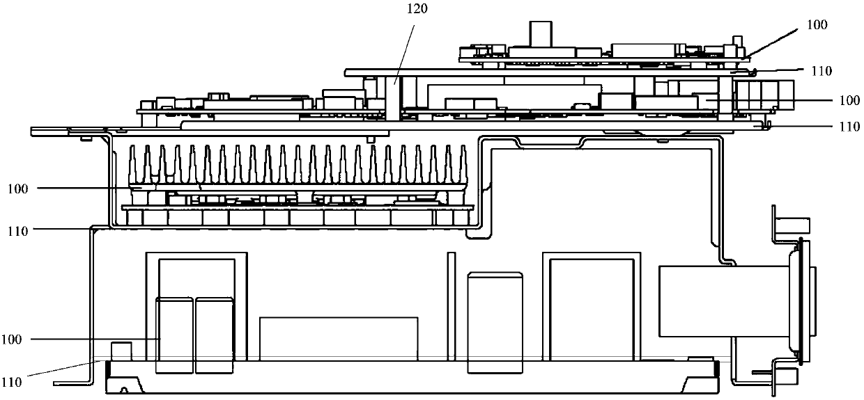
[0046] Figure 6 It is a schematic structural diagram of laser cinema equipment according to an embodiment of the present invention.

[0047] see Figure 6 , The laser cinema equipment provided by the embodiment of the present invention includes: a housing 610 , a ground plane is installed on the base of the housing 610 , and the ground plane has a bottom plate 621 and a side plate 622 perpendicular to the bottom plate 621 . A light source 630, an optical engine 631, a fan 632, a radiator 633, a display board 634, a TV board 635, an audio board 636, a wireless fidelity & bluetooth board 637, a power board 638, etc. are installed on the bottom board 621. Wherein, a plurality of circuit boards such as the display board 634, the TV board 635, the sound effect board 636, the Wi-Fi & Bluetooth board 637, etc. are respectively fixed on the multiple side boards 622 perpendicular to the bottom board 621, and the circuit boards board ground. Thus, the plurality of circuit boards are...


PUM


Abstract

The invention provides laser cinema equipment. A circuit system framework of electronic equipment comprises a shell; a ground plane plate is mounted on a base of the shell; the ground plane plate is provided with a bottom plate and side plates perpendicular to the bottom plate; a light source and an optical machine are mounted on the bottom plate; the circuit system framework further comprises atleast two circuit boards; the at least two circuit boards are mounted on the bottom plate and the side plates; the at least two circuit boards are grounded; and the circuit board mounted on the bottomplate is a power supply board. According to the laser cinema equipment provided by the embodiment of the invention, one complete and uniform large-area ground plane plate is formed by the bottom plate and the side plates, so that a complete ground circuit can be provided for backflow of an electric signal, and the serious EMI problem caused by the electronic equipment is prevented.

Description

technical field [0001] The invention relates to the field of electronic products, in particular to an electronic equipment circuit system architecture and laser cinema equipment. Background technique [0002] With the development of modern society, the functions of household electronic equipment are becoming more and more abundant; at the same time, in order to facilitate installation and use, the volume of electronic equipment is also getting smaller and smaller. For example, laser cinema TV, which is currently attracting much attention, has the functions of cinema, smart TV and home audio, and is welcomed by the home and commercial markets. [0003] Laser theater TV products use the structure of a projector, but at the same time have the function of a smart TV. In addition to modules such as optical engines, radiators, and fans, the internal structure also includes power boards, TV boards, display boards, wireless fidelity (Wireless Fidelity, referred to as: WIFI) & Bluet...

Claims


Application Information

Patent Timeline
Patent Type & Authority Patents(China)
IPC IPC(8): H05K9/00
CPCH05K9/0064
Inventor 陈昆明
Owner QINGDAO HISENSE LASER DISPLAY CO LTD
Why Eureka
Try Eureka