Energy operating device
A surgical device and energy technology, used in surgery, parts of surgical instruments, medical science, etc., can solve the problems of excessive incision of biological tissue and insertion of biological tissue.
- Summary
- Abstract
- Description
- Claims
- Application Information
AI Technical Summary
Problems solved by technology
Method used
Image
Examples
no. 1 Embodiment approach
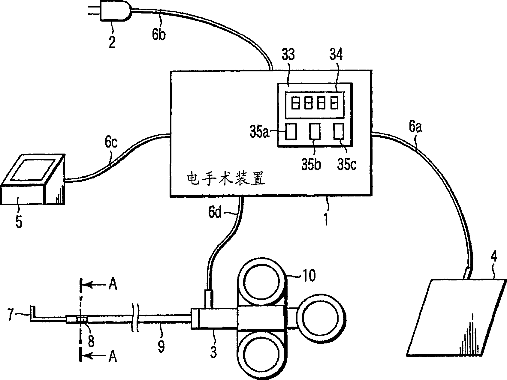
[0031] Below, use Figure 1 ~ Figure 7B The first embodiment of the present invention will be described. The energy surgery apparatus according to the present embodiment has: a state change detection unit that detects a state change of the electric scalpel as a treatment unit, for example, a force applied to the electric scalpel, and an adjustment unit that detects a state change based on the detection result of the state change detection unit. The amount of energy supplied to the treatment unit can be adjusted. With such a configuration, the energy surgery device of this embodiment can adjust the treatment amount of the treatment unit for the subject.
[0032] figure 1 It is a figure for demonstrating the outline|summary of 1st Embodiment. exist figure 1 In this case, the energy instruction input unit 105 receives an instruction to supply energy to the processing unit 101 from the operator. The energy indication input unit 105 transmits the indication input signal to the ...
no. 2 Embodiment approach
[0057] Below, the main use Figure 8 ~ Figure 12 A second embodiment of the present invention will be described.
[0058] Figure 8 It is a figure for demonstrating the outline|summary of 2nd Embodiment. exist Figure 8 Among them, the power instruction input unit 126 receives an instruction for operating the processing unit 122 from the operator 128 . Furthermore, the energy instruction input unit 127 receives an instruction to supply energy to the processing unit 122 from the operator 128 . The power instruction input unit 126 transmits a signal related to the power instruction to the control unit 125-1. The energy instruction input unit 127 transmits an instruction related to the energy instruction to the adjustment unit 125-2.
[0059] Furthermore, the state change detection unit 123 transmits the state change of the processing unit 122 to the adjustment unit 125-2. The control unit 125-1 determines the output to the power unit 121 based on the signal from the power ...
no. 3 Embodiment approach
[0090] Below, the main use Figure 13 ~ Figure 15 A third embodiment of the present invention will be described. Figure 13 It is a figure which shows the structure of 3rd Embodiment of this invention. The basic structure of electrosurgical device 1 and figure 1 The structure shown in the first embodiment is the same as that shown in the first embodiment, but here, the difference is that an electric scalpel 50 for laparoscopic surgery is connected instead of the flexible mirror electric scalpel 3 .
[0091] Figure 14 It is a diagram showing the internal structure of the electrosurgical device 1 . This internal structure is also Figure 4 The same as the 1st way. Structural action of the third embodiment and Figure 5 The flow charts shown are the same, so detailed explanations are omitted here.
[0092] Next, use Figure 15 The details when the third embodiment is applied to endoscopic surgery will be described. Figure 15 It is a cross-sectional view of the human ab...
PUM
 Abstract
Description
Claims
Application Information
 - R&D
- Intellectual Property
- Life Sciences
- Materials
- Tech Scout
- Unparalleled Data Quality
- Higher Quality Content
- 60% Fewer Hallucinations
Browse by: Latest US Patents, China's latest patents, Technical Efficacy Thesaurus, Application Domain, Technology Topic, Popular Technical Reports.
© 2025 PatSnap. All rights reserved.Legal|Privacy policy|Modern Slavery Act Transparency Statement|Sitemap|About US| Contact US: help@patsnap.com


