
An improved by-pass and pressure regulator valve

一种压力调节、旁通口的技术,应用在多通阀、无辅助动力的流体压力控制、阀细节等方向,能够解决尺寸增大、构造复杂等问题,达到部件简化、校准容易、生产过程简化的效果

Active Publication Date: 2009-08-26
P A S P A RUBIERA
View PDF0 Cites 8 Cited by
  • Summary
  • Abstract
  • Description
  • Claims
  • Application Information

AI Technical Summary

Problems solved by technology

[0009] But the valves described above present an important problem: in order to keep the obturator closed, the adjustment spring must be contrasted
But the presence of these two different obturators leads to undesired size increase and excessive constructional complexity

Method used


Image

  • An improved by-pass and pressure regulator valve
  • An improved by-pass and pressure regulator valve
  • An improved by-pass and pressure regulator valve

Examples


Embodiment Construction

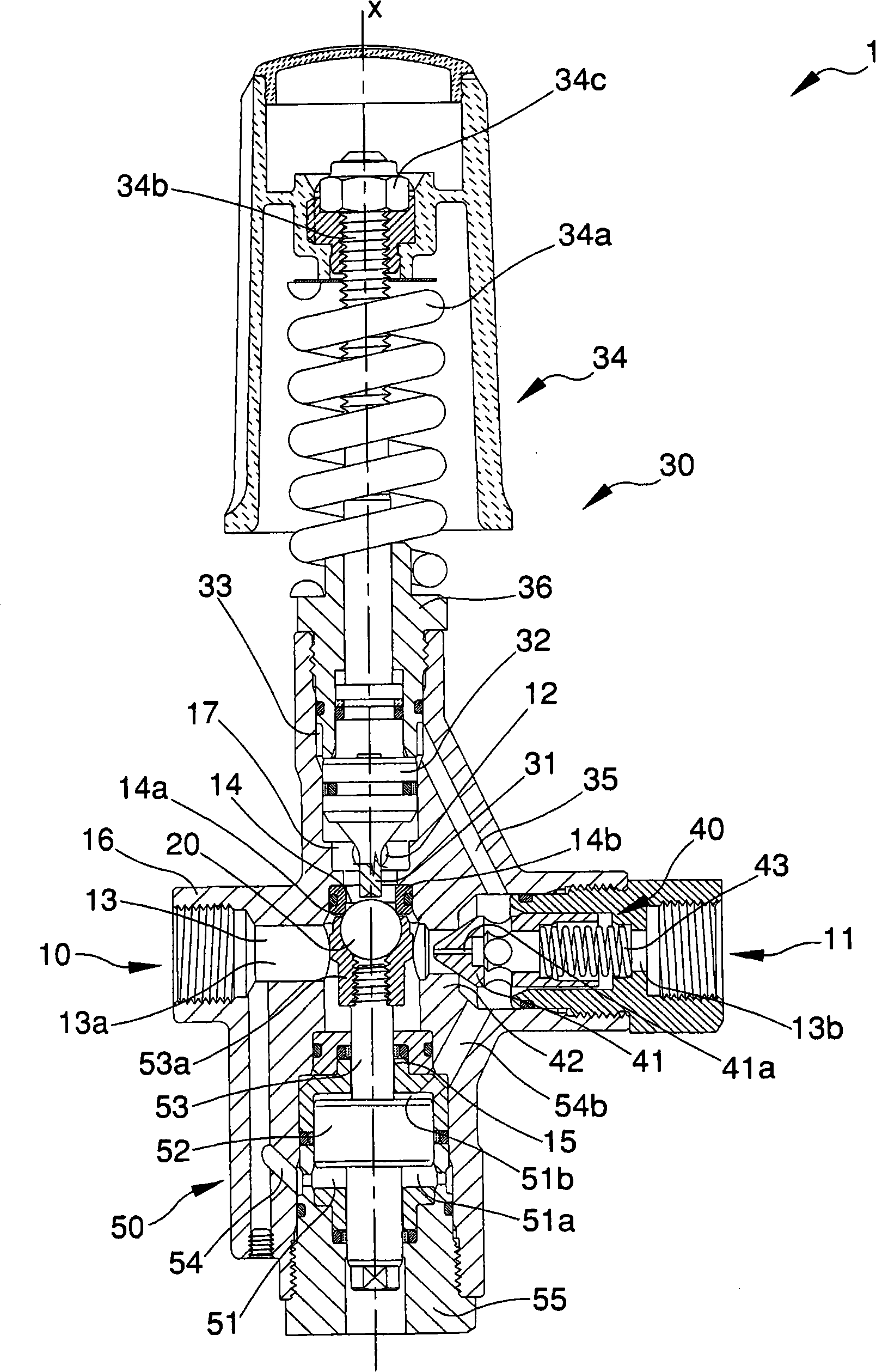
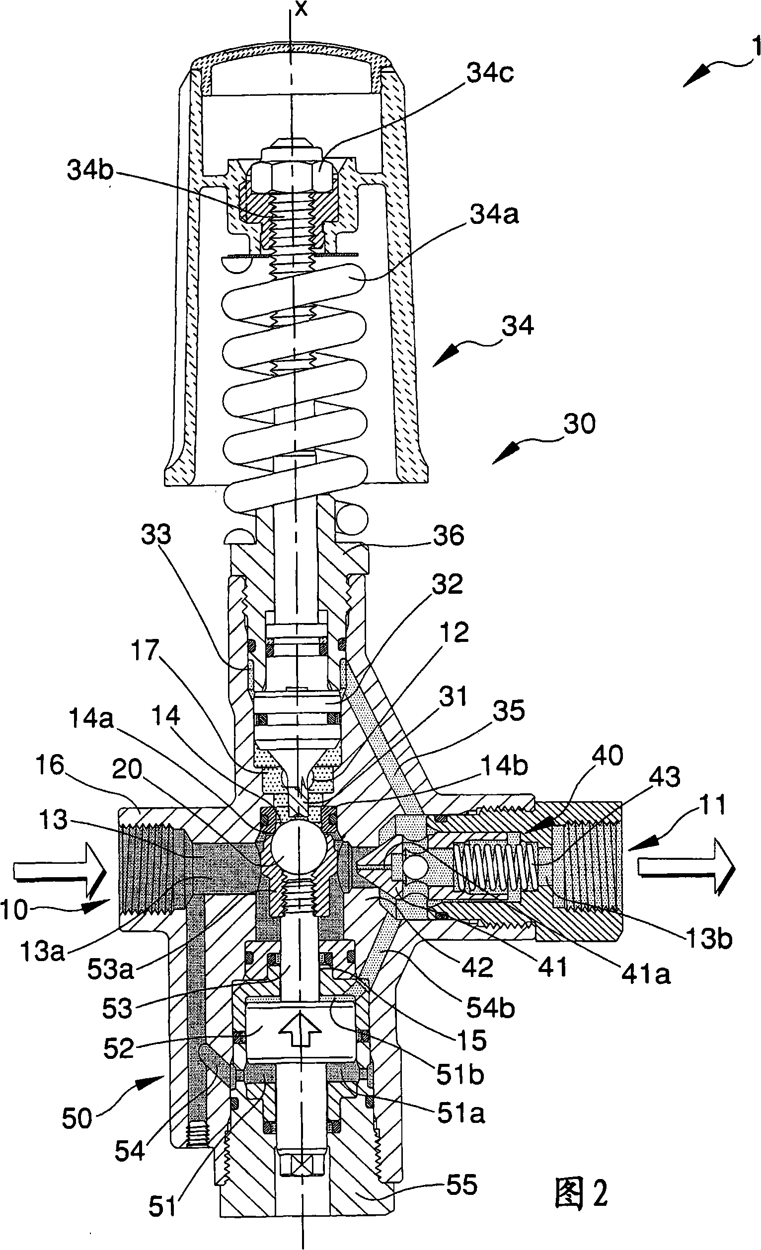
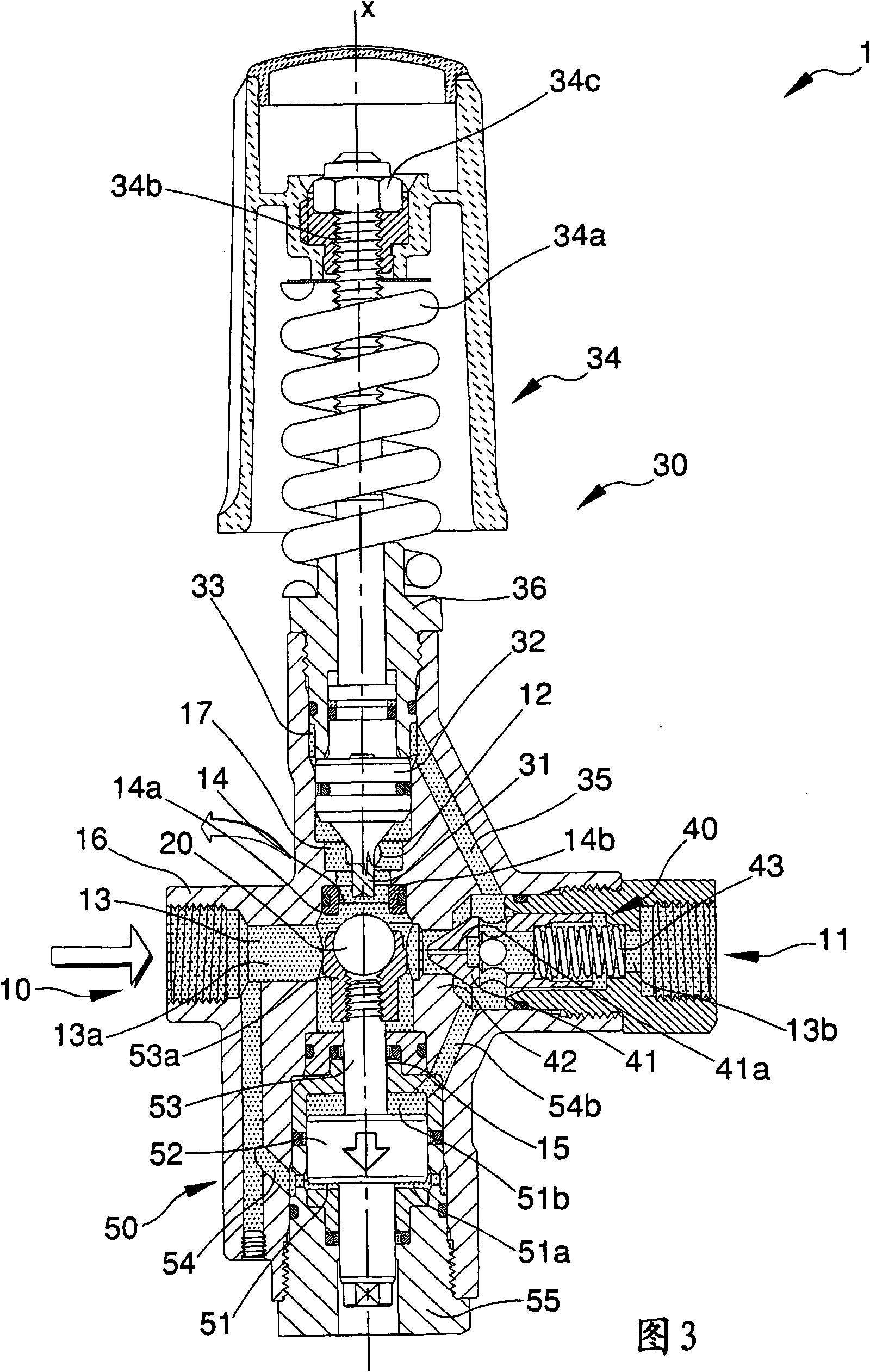
[0025] Referring to accompanying drawing, 1 represents bypass pressure regulating valve of the present invention. In particular, this valve is preset to reduce the pressure in the delivery branch stream up to slightly above atmospheric pressure when the gun in the relevant circuit is closed, ie it is of the type of valve commonly known as a reset valve.

[0026] The device is illustrated in a preferred operating configuration. The positional relationship between elements of the bypass pressure regulating valve 1 hereinafter described with relative heights (for example, by using words like "lower" or "higher") will always be explained with reference to this configuration.

[0027] The bypass pressure regulating valve 1 of the present invention shows an inlet 10 and an outlet 11 arranged to communicate with each other through a main pipe 13 ; it further has a bypass port 12 .

[0028] The bypass pressure regulating valve 1 includes an obturator 20 movable at least between a clo...


PUM


Abstract

A by-pass and pressure regulator valve (1), comprising:: an inlet mouth (10) and an outlet mouth (11) set in reciprocal communication by a main conduit (13); a by-pass mouth (12). The by-pass and pressure regulator valve (1) comprises: an obturator (20), mobile between at least a closed position which interrupts fluid communication between the main conduit (13) and the by-pass mouth (12), and at least an open position, in which the fluid communication is not interrupted; operating pressure control means (30), predisposed to move the obturator (20) from the closed position; means for determining a flow pressure loss (40) in fluids crossing the main conduit (13), arranged along the main conduit (13) in order to separate a first tract (13a) upstream of the main conduit (13) from a second tract (13b) downstream thereof; obturator (50) command means governed by a fluid pressure difference between the first tract (13a) and the second tract (13b) of the main conduit (13), distinct from the operating pressure control means (30) but operatively connected to the obturator (20).

Description

technical field [0001] The object of the invention is a bypass pressure regulating valve. In particular, the valve is effectively used inside a hydraulic circuit for high-pressure washing. Background technique [0002] High pressure washing equipment typically includes a piston pump designated for placing washing fluid under pressure, a valve of the type of the present invention and a lever tap valve, often called a gun, pre-set to enable an operator to control the dispensing of the fluid . [0003] The pump will operate continuously if there is no electrical means for automatically shutting off the pump, so it will remain running even if the operator has shut off the gun; assuming the fluid is incompressible, it will be necessary to drain the fluid into the low pressure tank through a bypass line. The opening of this line is controlled by a valve known simply as a bypass valve or unloading valve. [0004] This valve is also used to control the operating pressure as the g...

Claims


Application Information

Patent Timeline
Patent Type & Authority Applications(China)
IPC IPC(8): F16K17/32F16K11/00F16K47/00F16K27/00B08B3/02
CPCG05D16/10Y10T137/2516Y10T137/2605Y10T137/2647Y10T137/265
Inventor A·贝内蒂
Owner P A S P A RUBIERA
Learn More