
Time-to-digital conversion circuit and correlation method thereof

A time-to-digital conversion, circuit technology, applied in the direction of electrical unknown time interval measurement, devices and instruments for measuring time interval, etc.

Active Publication Date: 2009-08-26
REALTEK SEMICON CORP
View PDF0 Cites 14 Cited by
  • Summary
  • Abstract
  • Description
  • Claims
  • Application Information

AI Technical Summary

Problems solved by technology

[0003] However, in such an approach, it is often necessary to use the entire delay circuit, so the circuit will have a larger area

Method used


Image

  • Time-to-digital conversion circuit and correlation method thereof
  • Time-to-digital conversion circuit and correlation method thereof

Examples


Embodiment Construction

[0023] In the specification and the above-mentioned patent application, certain words are used to refer to specific elements. Those skilled in the art should understand that hardware manufacturers may use different terms to refer to the same component. This specification and the aforementioned scope of patent applications do not use differences in names as a way to distinguish elements, but use differences in functions of elements as a criterion for distinguishing. The "include" mentioned in the entire manual and the above request is an open term, so it should be interpreted as "include but not limited to". In addition, the term "coupling" here includes any direct and indirect electrical connection means. Therefore, if it is described in the text that the first device is coupled to the second device, it means that the first device can be directly electrically connected to the second device, or indirectly electrically connected to the second device through other devices or connecti...


PUM


Abstract

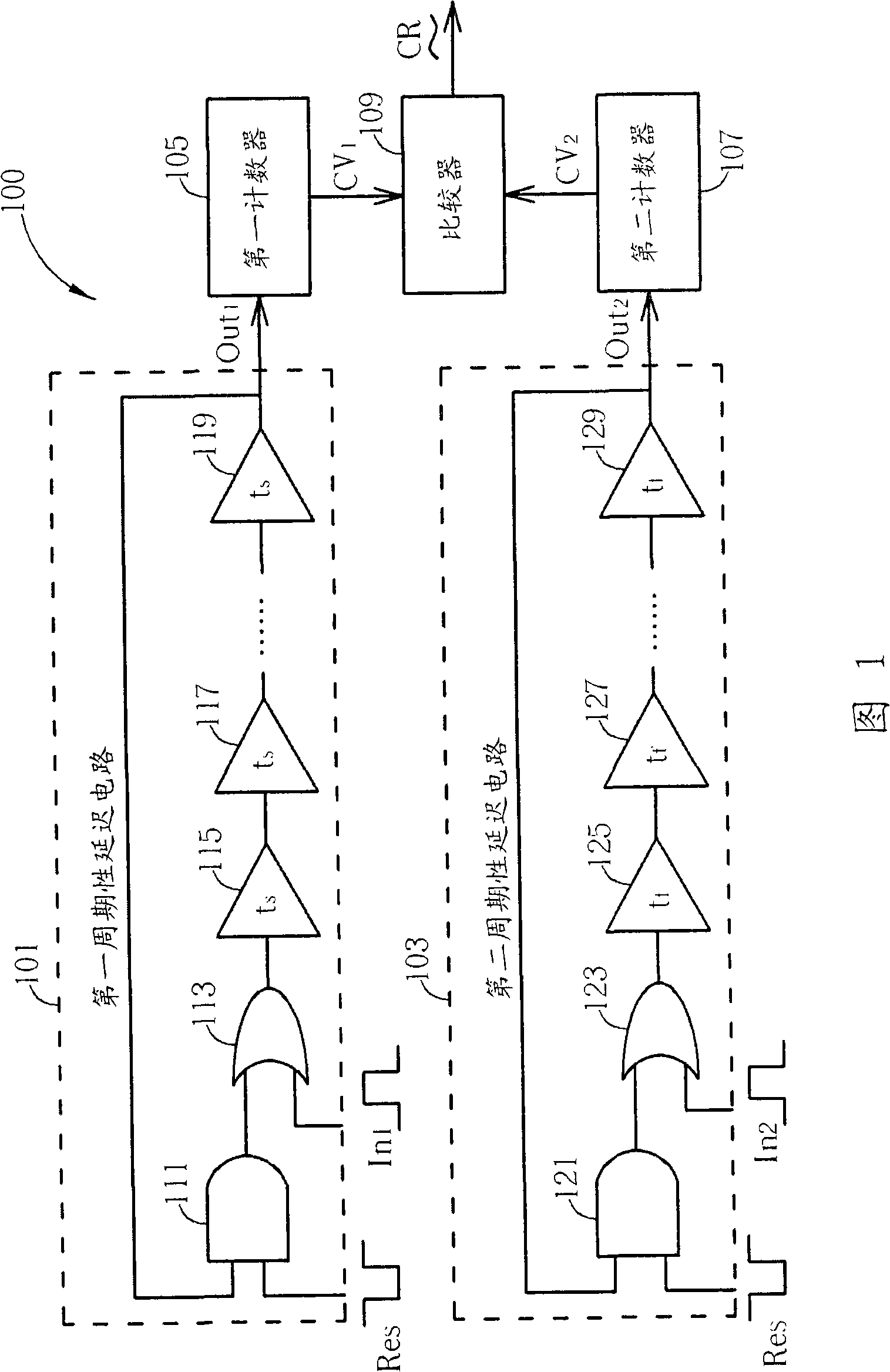
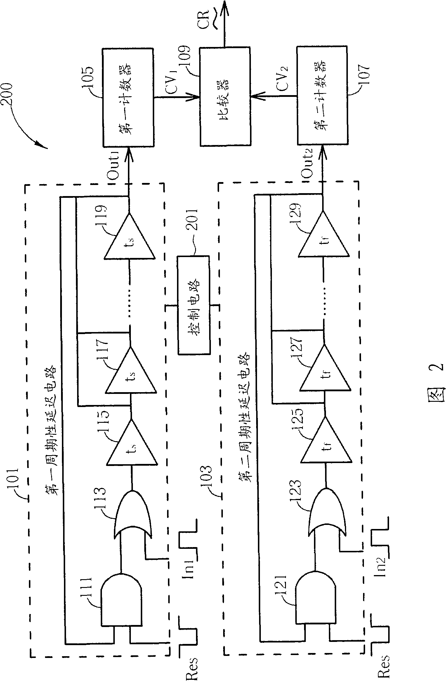
The invention provides a time-to-digital conversion circuit, which comprises a first delay circuit, a second delay circuit, a first counter, a second counter and a comparator, wherein the first delay circuit is provided with a first delay level and used for delaying a first input signal to generate a first output signal; the second delay circuit is provided with a second delay level and used for delaying a second input signal to generate a second output signal; the first counter is used for counting the first output signal to generate a first counting value; the second counter is used for counting the second output signal to generate a second counting value; the comparator is used for comparing the first counting value with the second counting value to generate a comparison result signal; the first delay level has larger delay quantity than the second delay level; the first counter begins to count earlier compared with the second counter; and when the second counting value is within a preset range comprising the first counting value, the comparator outputs the comparison result signal.

Description

Technical field [0001] The present invention relates to a time-to-digital conversion circuit, and more particularly to a time-to-digital conversion circuit that uses a delay circuit to generate a periodic delay signal. Background technique [0002] Generally speaking, a time to digital conversion circuit (Time to Digital Converting, TDC) is used to measure the degree of delay of a signal, so as to convert the degree of delay of the signal into the amount of delay of the actual delay stage, that is, to determine the degree of delay of the signal. The number of delay stages is expressed. The old method is to send the first signal and the second signal to the first delay circuit and the second delay circuit respectively, where the first signal (usually the signal to be measured) is sent in longer than the second signal (usually the signal to be measured). The known reference signal) is early, but the delay amount of the delay stage of the first delay circuit is larger than the delay...

Claims


Application Information

Patent Timeline
Patent Type & Authority Applications(China)
IPC IPC(8): G04F10/00G04F10/04
Inventor 陈逸琳
Owner REALTEK SEMICON CORP
Learn More