Method, system and device for time synchronous transfer

A technology of time synchronization and transmission system, applied in the field of communication, can solve the problem of synchronization error without compensation

Active Publication Date: 2009-08-26
NEW H3C TECH CO LTD
View PDF1 Cites 83 Cited by
  • Summary
  • Abstract
  • Description
  • Claims
  • Application Information

AI Technical Summary

Problems solved by technology

[0006] However, in a synchronous communication network that requires multi-level node device interconnection, one port of a device to another port may require internal multi-level time synchronization
The existing synchronization technology does not compensate for the synchronization error caused by the PPS transmission delay. This error will monotonically accumulate step by step. It cannot be guaranteed that the synchronization error will still be less than the microsecond level in the case of multi-level equipment cascading.

Method used


Image

  • Method, system and device for time synchronous transfer
  • Method, system and device for time synchronous transfer
  • Method, system and device for time synchronous transfer

Examples


Embodiment Construction
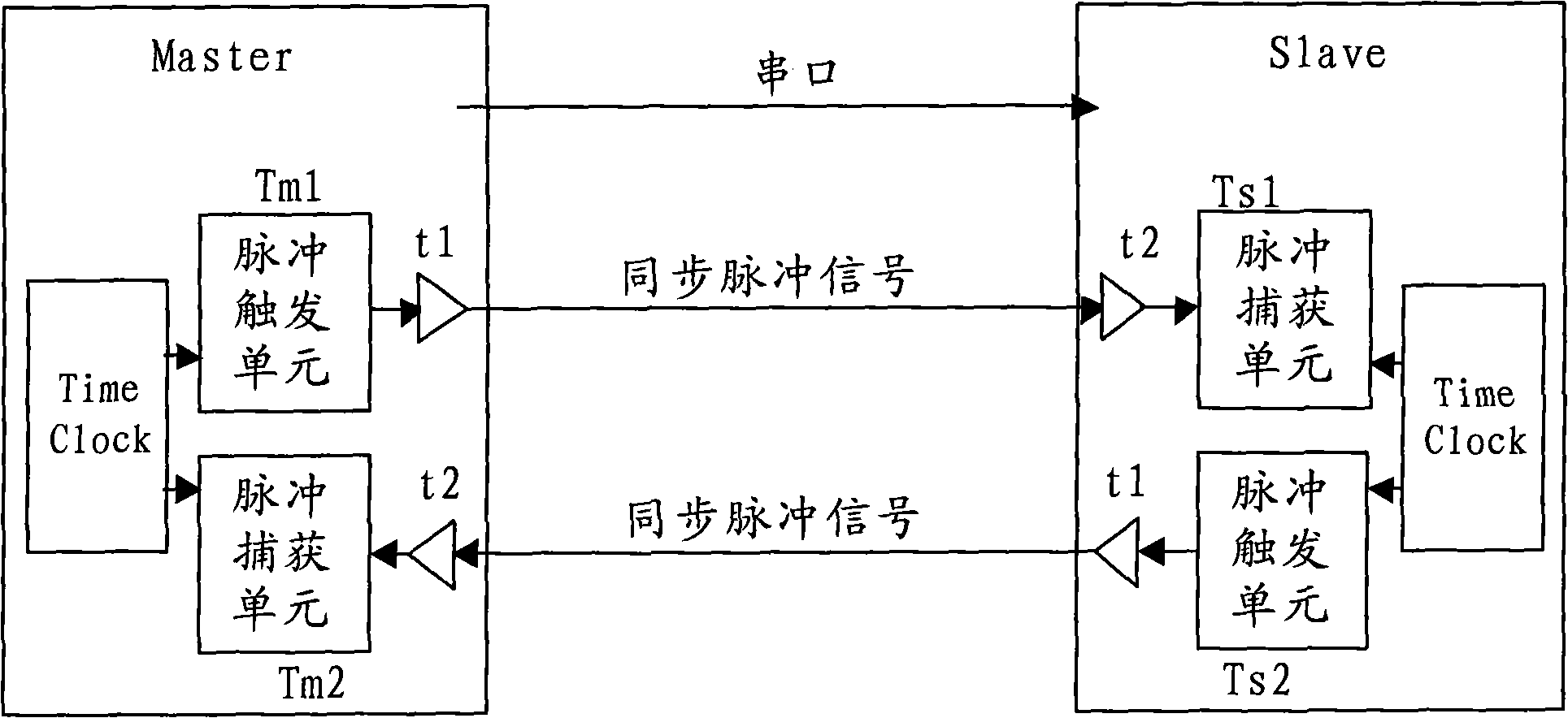
[0101] The core idea of ​​the present invention is to obtain the transmission delay of the synchronization pulse, calculate the transmission delay of the synchronization pulse into the time deviation between the master device and the slave device, adjust the synchronization clock of the slave device according to the time deviation, and reduce the PPS The synchronization error caused by the transmission delay ensures that the synchronization error is less than microsecond level.

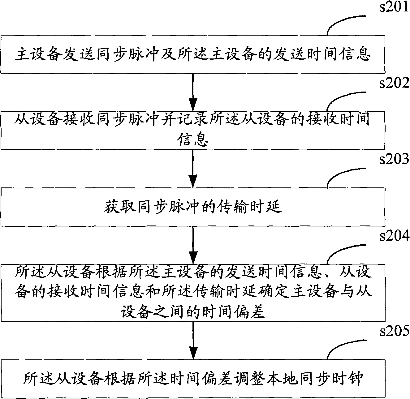
[0102] The present invention provides a time synchronization transfer method, which is applied to a system including a clock master device and a clock slave device. The method is as figure 2 As shown, it includes the following steps:

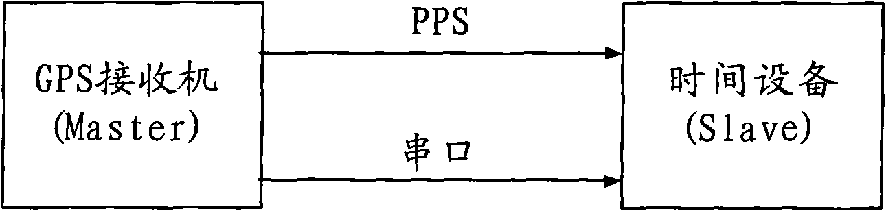
[0103] Step 201: The master device sends a synchronization pulse and the sending time information (for example, a timestamp) of the master device.

[0104] Step 202: The slave device receives the synchronization pulse and records the receiving time information of the slave...


PUM


Abstract

The invention discloses a method for time synchronous transfer, which comprises the following steps: transmitting a synchronous pulse and transmitting time information of a main device by the main device; receiving the synchronous pulse and recording received time information of a slave device by the slave device; acquiring the transmission time delay of the synchronous pulse; determining the time deviation between the main device and the slave device by the slave device according to the transmitted time information of the main device, the received time information of the slave device and thetransmission time delay; and adjusting a local synchronous clock by the slave device according to the time deviation. The invention also discloses a system and a device for the time synchronous transfer. The method, the system and the device obtain the synchronous errors among devices and compensate the clock according to the synchronous errors so as to reduce the synchronous errors caused by thetransfer time delay of PPS and ensure that the synchronous errors of the cascade connection of a multilevel device are still lower than microsecond level.

Description

Technical field [0001] The present invention relates to the field of communication technology, in particular to a time synchronization transfer method, system and device. Background technique [0002] In the process of transforming to next-generation networks, all levels of networks such as mobile networks and fixed networks, as well as core networks, transport networks, and access networks have put forward new requirements for synchronization. For example, in the use of CDMA2000 (Code Division Multiple Access 2000, Code Division Multiple Access 2000) and TD-SCDMA (Time Division-Synchronous Code Division Multiple Access, Time Division Synchronous Code Division Multiple Access) two standards, 3G (3th Generation, In the third-generation network, high-precision time synchronization is required between base station systems, for example, better than 10 μs (subtle). Because in soft handover, if there is no time synchronization between RNC (Radio Network Control) and NodeB (base station...

Claims


Application Information

Patent Timeline
Patent Type & Authority Applications(China)
IPC IPC(8): H04J3/06H04B7/26
Inventor 魏初舜于洋
Owner NEW H3C TECH CO LTD
Why Eureka
Try Eureka