Heat exchanger and method for manufacturing same

A technology for heat exchangers and manufacturing methods, which is applied in the direction of heat exchange equipment, indirect heat exchangers, heat exchanger types, etc., can solve the problems of heat exchanger performance degradation, fluid dispersion, and pressure loss increase, so as to improve heat Exchange performance, improve pressure resistance, improve the effect of bias current

Inactive Publication Date: 2009-08-26
SANYO ELECTRIC CO LTD +1
View PDF1 Cites 7 Cited by
  • Summary
  • Abstract
  • Description
  • Claims
  • Application Information

AI Technical Summary

Problems solved by technology

[0005] However, the above-mentioned fins are arranged in the flat container so that the fins face any direction perpendicular to or parallel to the flow direction of the fluids flowing in the flow path. If the fins are arranged to be perpendicular to the flow direction of the fluid, the The area where the fluid collides with the fins is large, so the fluid is easily dispersed to the entire flow path due to the action of the fins, so that the fluid can flow uniformly throughout the flow path, but there is a problem that the pressure loss will increase significantly
[0006] On the other hand, if the fins are arranged parallel to the flow direction of the fluid, the pressure loss is small because the area where the fluid collides with the fins is small, but it is difficult to disperse the fluid to the entire flow path, so the fluid cannot flow through the entire flow path. Flows evenly, resulting in significantly reduced performance as a heat exchanger

Method used


Image

  • Heat exchanger and method for manufacturing same
  • Heat exchanger and method for manufacturing same
  • Heat exchanger and method for manufacturing same

Examples


Embodiment Construction

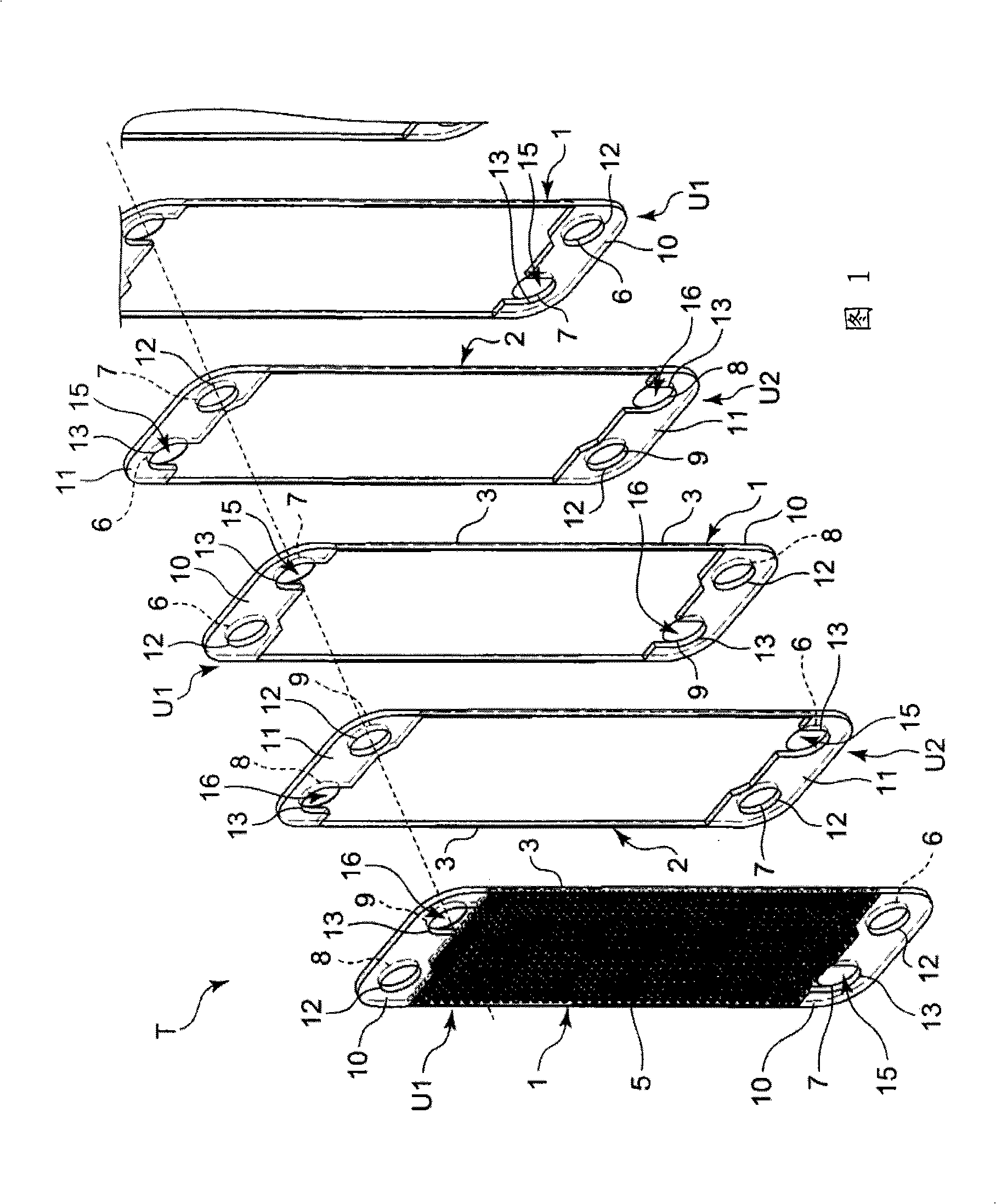
[0046] The present invention relates to a heat exchanger for exchanging heat between fluids, and aims to improve the problem of increased pressure loss when the fins are arranged perpendicular to the flow direction of the fluid, and to improve the problem of increasing the pressure loss when the fins are arranged perpendicular to the flow direction of the fluid. Fluid deflection when parallel. By arranging the fin orthogonal region where the fin is perpendicular to the flow direction of the fluid from the inlet toward the outlet, and the fin parallel region where the fin is parallel to the flow direction of the fluid from the inlet toward the outlet, the The purpose of suppressing pressure loss while improving the uneven velocity distribution of the fluid. Embodiments of the present invention will be described in detail below with reference to the accompanying drawings.

[0047] figure 1 is a perspective view schematically showing the structure of a heat exchanger according ...


PUM


Abstract

Provided is a heat exchanger which can suppress increase of pressure loss while improving nonuniform speed distribution of a fluid. In the heat exchanger (T), a fluid channel (4) is composed of flat containers (1, 2) having an inflow port (15) for the fluid at one end section and an outflow port (15) for the fluid at the other end section, and an offset type fin (5) arranged in the flat containers (1, 2). The heat exchanger is provided with a fin orthogonal intersection region (H) where the plate fin (5) orthogonally intersects with a flow direction of the fluid flowing from the inflow port (15) to the outflow port (16), and a fin parallel region (V) wherein the plate fin (5) is parallel to the flow direction of the fluid flowing from the inflow port (15) to the outflow port (16). The fin orthogonal intersection regions (H) are arranged on the sides of the inflow port (15) and the outflow port (16), and the fin parallel region (V) is arranged between the fin orthogonal intersection regions (H).

Description

technical field [0001] The present invention relates to a heat exchanger for exchanging heat between a first fluid and a second fluid and a manufacturing method thereof. Background technique [0002] Such a heat exchanger is, for example, a heat exchanger provided with offset fins, and is configured to have a plurality of flat containers and offset fins provided at one end in the longitudinal direction of the flat container. between the inlet and the outlet formed at the other end. In this flat container, a flow path for a fluid entering from an inlet at one end, passing between the fins toward the other end, and flowing out through an outlet is formed. [0003] The above-mentioned fins are formed by providing a pair of cutouts at regular intervals from the shoulder to the plate portion on both side walls of the rib having a trapezoidal cross-section, and bending the portion inward to assume the above-mentioned offset shape. In addition, it is generally constituted as foll...

Claims


Application Information

Patent Timeline
Patent Type & Authority Applications(China)
IPC IPC(8): F28F3/08F25B1/00F25B39/00F28D9/02F28F1/40
CPCF28D9/005F28F3/027F25B39/00Y10T29/49378
Inventor 友近一善泽田范雄向山洋松康太郎
Owner SANYO ELECTRIC CO LTD
Why Eureka
Try Eureka