
Wind turbine energizer

A technology for wind turbines and energizers, which can be applied to wind turbines, wind power generation, and wind turbines in the same direction as the wind, and can solve problems such as relatively little attention.

Inactive Publication Date: 2018-06-26
BEIHANG UNIV
View PDF5 Cites 4 Cited by
  • Summary
  • Abstract
  • Description
  • Claims
  • Application Information

AI Technical Summary

Problems solved by technology

[0004] On the other hand, to date, a large amount of investment has been invested in blade design, tower design, engine design, etc., and relatively little attention has been paid to the issue of airflow into the wind turbine

Method used


Image

  • Wind turbine energizer
  • Wind turbine energizer
  • Wind turbine energizer

Examples


Embodiment Construction

[0016] To solve the above problems of the prior art, the present invention relates to the optimization of the airflow entering the wind turbine on the one hand, and provides a solution to improve the velocity distribution of the airflow in front of the wind turbine impeller on the other hand.

[0017] The invention provides an energy booster for a wind turbine, which is used as a tool for changing the airflow state in front of the wind wheel of the wind turbine by using the principle of aerodynamics.

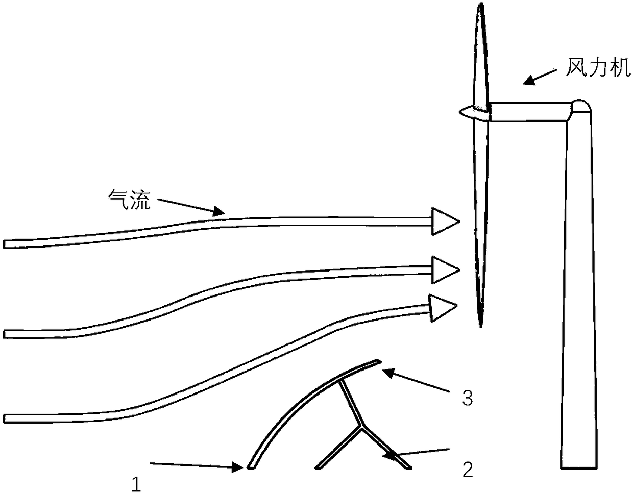
[0018] The structure and configuration of the wind turbine booster according to an embodiment of the present invention are as follows figure 2 As shown, wherein, the wind turbine booster includes a deflector 3 and a support structure 2 . Wherein, the support structure 2 supports the deflector 3 . At least a part of the deflector 3 is arranged at a position upstream of the airflow of the wind turbine blade.

[0019] According to the principle of the wind turbine energy booster...


PUM


Abstract

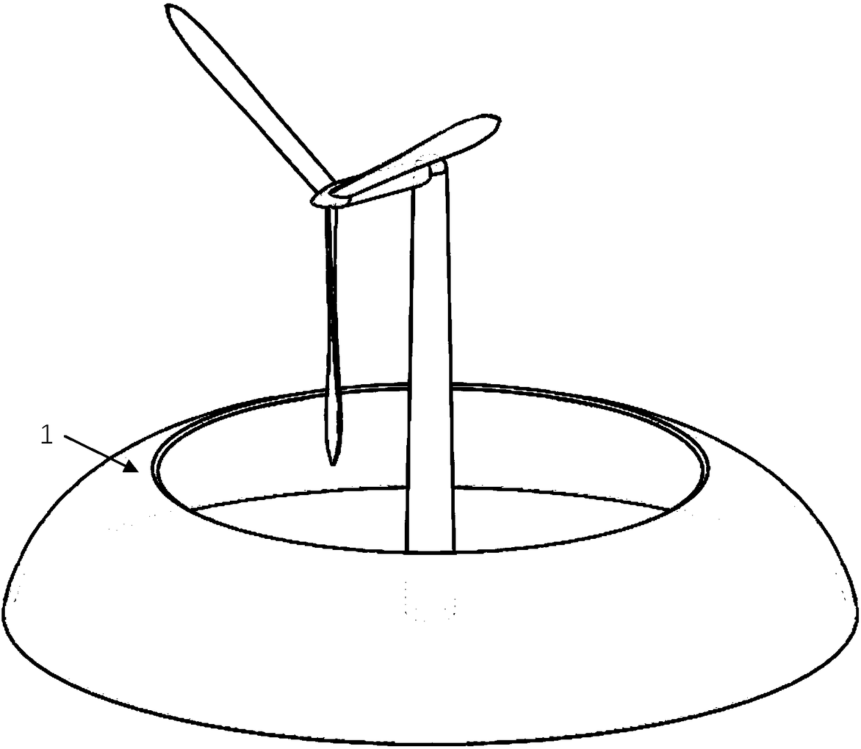
The invention provides a wind turbine energizer (1) based on aerodynamics for a wind driven generator. The wind turbine energizer comprises a guide plate (3) arranged in front of a wind turbine and provided with a streamline section and a supporting structure (2) thereof. Based on different hub heights and blade lengths of the wind turbine, on the premise of not interfering in rotation of wind turbine blades and not generating harmful pneumatic interference, the wind turbine energizer (1) which is proper in size is arranged near the front of the wind turbine. By forming a shrinking channel inthe upstream part of an impeller of the wind turbine, the average speed of an air flow in a region of the impeller of the wind turbine is improved, the speed is more uniformly distributed, and therefore, the efficiency of the wind turbine is improved, the starting air speed of the wind turbine is reduced, the operation stability of a wind wheel is improved, the external torque subjected to a rotary shaft of the wind wheel is reduced, and the service lives of the blades, hubs and a transmission system are prolonged.

Description

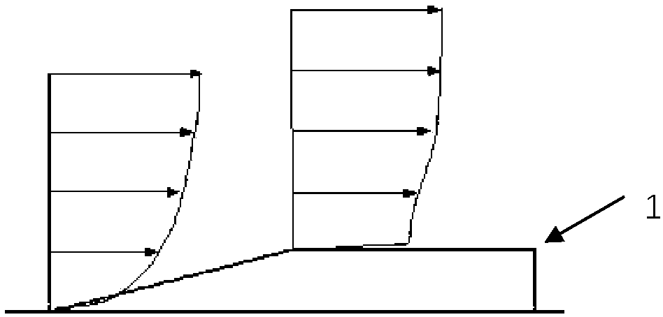
technical field [0001] The invention relates to a wind power generator. technical background [0002] Among various renewable energy sources, wind energy is a relatively mature technology. [0003] Due to the existence of the ground boundary layer of the atmosphere, the wind speed near the ground is close to zero, and the speed of the airflow can only reach a higher level at a certain height, which makes the airflow speed passing through the wind turbine impeller have a non-negligible loss. And because there is a large velocity gradient in the atmospheric boundary layer, the wind turbine rotor is subjected to periodic uneven loads during operation, which will cause periodic fatigue damage to the wind turbine blades and wear of the wind turbine mechanical transmission structure. increase. Improving the velocity distribution of the airflow in front of the wind turbine impeller is the key to solving the above problems. [0004] On the other hand, to date, a large amount of i...

Claims


Application Information

Patent Timeline
IPC IPC(8): F03D1/04H02S10/12
CPCF03D1/04H02S10/12Y02E10/50Y02E10/72
Inventor 杜刚巴剑铭程京生
Owner BEIHANG UNIV
Learn More