Electronic part cooler

a technology of electronic components and coolers, applied in semiconductor devices, semiconductor/solid-state device details, lighting and heating apparatus, etc., can solve the problem of unavoidable increase in the amount of heat generated in accompaniment to increased output, and achieve the effect of increasing the cooling effect of electronic components

Active Publication Date: 2017-01-26
FUJI ELECTRIC CO LTD
View PDF4 Cites 4 Cited by
  • Summary
  • Abstract
  • Description
  • Claims
  • Application Information

AI Technical Summary

Benefits of technology

[0009]The technologies described in JPA 2012-174963 and WO 2011 / 132736 both have an aspect of correcting bias in an amount of refrigerant distributed from an introduction flow path to a cooling path disposed in parallel, thereby evenly cooling a cooled surface.
[0010]However, a method of improving velocity distribution in a refrigerant introduction flow path cross-section, thereby increasing cooling efficiency, is not discussed in the heretofore described existing technology.
[0011]Therefore, an aspect of the disclosure is to provide an electronic component cooler such that velocity distribution in a refrigerant introduction flow path cross-section is improved, thereby increasing cooling efficiency.
[0022]According to the disclosure, using a protruding portion disposed on a cooling surface side of a refrigerant introduction flow path, velocity distribution can be formed so that a portion that comes into contact with the protruding portion is of a high velocity. Therefore, a portion of refrigerant flowing in from cooling fin refrigerant introduction side openings that comes into contact with a first wall portion forming a cooling surface can be caused to flow faster, because of which an electronic component cooling effect can be increased.

Problems solved by technology

Although a power semiconductor element is designed in such a way that on-state resistance is lowered, an increase in the amount of heat generated in accompaniment to increased output is unavoidable, and coolers from air cooling types to liquid cooling types have already been employed in a semiconductor module in which a multiple of power semiconductor elements are mounted, and the like.

Method used


Image

  • Electronic part cooler
  • Electronic part cooler
  • Electronic part cooler

Examples


Embodiment Construction

[0028]Hereafter, referring to the drawings, a description will be given of an embodiment of an electronic component cooler according to the disclosure.

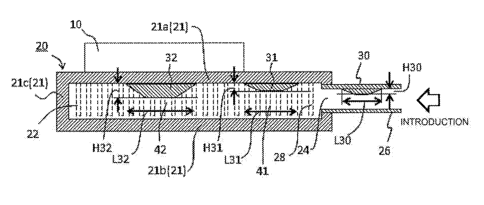
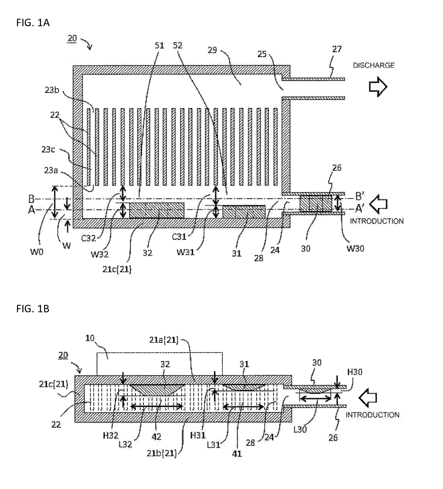
[0029]A plan view of the cooler is shown in FIG. 1A, and an A-A′ sectional view of FIG. 1A is shown in FIG. 1 B. A cooler 20 has a cooler main body 21 formed of a first wall portion 21a functioning as a cooling surface that cools an electronic component 10, a second wall portion 21b disposed opposing the first wall portion 21a, and a side wall portion 21c enclosing the first wall portion 21a and second wall portion 21b.

[0030]In order to effectively cool the electronic component 10, cooling fins 22 are attached to an internal surface of the first wall portion 21a. Any type of fin, such as a blade fin, corrugated fin, or pin fin, can be used as the cooling fin 22. Blade fins and corrugated fins may be of a straight form so as to form a straight flow path, but waving fins wherein the fins are caused to undulate in a wave form so that th...


PUM


Abstract

A cooler with a cooler main body that, in one configuration, includes a first wall portion forming a cooling surface that cools an electronic component, a second wall portion disposed opposing the first wall portion, and a side wall portion that connects a periphery of the first wall portion and a periphery of the second wall portion. In the configuration, cooling fins are attached to an inner wall surface of the first wall portion, a refrigerant introduction pipe and refrigerant introduction flow path for supplying refrigerant to the cooling fins and a refrigerant discharge pipe and refrigerant discharge flow path for ejecting refrigerant from the cooling fins are included, and protruding portions and are provided on the first wall portion side of the refrigerant introduction flow path.

Description

CROSS-REFERENCE TO RELATED APPLICATIONS[0001]This application is a continuation application, filed under 35 U.S.C. §111(a), of International Application PCT / JP2015 / 073578 filed on Aug. 21, 2015 and claims foreign priority to Japanese Patent Application No. 2014-192123, filed Sep. 22, 2014, the content of each of which is incorporated herein by reference in its entirety.BACKGROUND[0002]1. Field[0003]The present disclosure relates to a cooler that cools an electronic component, and relates to a cooler wherein velocity distribution in a refrigerant introduction flow path is improved, thus increasing an electronic component cooling effect.[0004]2. Related Art[0005]The introduction of a power supply and motor which is used in an inverter circuit with high energy conversion efficiency, and a hybrid car, electric vehicle, or the like in which the power supply and motor are put to practical use, is accelerating with a view to realizing a low-carbon society. In these fields, an electronic co...

Claims


Application Information

Patent Timeline
Patent Type & Authority Applications(United States)
IPC IPC(8): H01L23/473H01L23/367
CPCH01L23/3675H01L23/473F28D15/0266H01L23/427H01L2924/0002
Inventor KOYAMA, TAKAHIRO
Owner FUJI ELECTRIC CO LTD
Why Eureka
Try Eureka