Device for detecting rotating position of superconductive spherical rotor

A technology of rotating position and spherical rotor, applied in the direction of measuring device, using electric device, using electro-magnetic device to transmit sensing components, etc., can solve the problem of installation error affecting driving efficiency, increasing device complexity and installation requirements, increasing control time, etc. problems, to achieve the effect of improving driving accuracy and efficiency, no energy loss, and simple installation

Inactive Publication Date: 2009-09-02
INST OF ELECTRICAL ENG CHINESE ACAD OF SCI
View PDF1 Cites 12 Cited by
  • Summary
  • Abstract
  • Description
  • Claims
  • Application Information

AI Technical Summary

Problems solved by technology

Foreign literature [K.F.Schoch, B.Darrel, A Superconducting Gyroscope for Gimballed Platform Application, GE Company Tech.Report, pp657-665, 1969] and Chinese patent 200810119566.0 both use sensors to measure the window on the top plane of the rotor Position mark, this method not only needs to install the sensor in the space above the rotor, but also needs to make a window position mark on the top plane of the rotor; it not only increases the complexity of the device and installation requirements, but also the manufacturing error of the mark and the installation error of the sensor will affect the rotor drive efficiency, increased control time

Method used


Image

  • Device for detecting rotating position of superconductive spherical rotor
  • Device for detecting rotating position of superconductive spherical rotor
  • Device for detecting rotating position of superconductive spherical rotor

Examples


Embodiment Construction

[0012] The present invention will be further described below in conjunction with the accompanying drawings and specific embodiments.

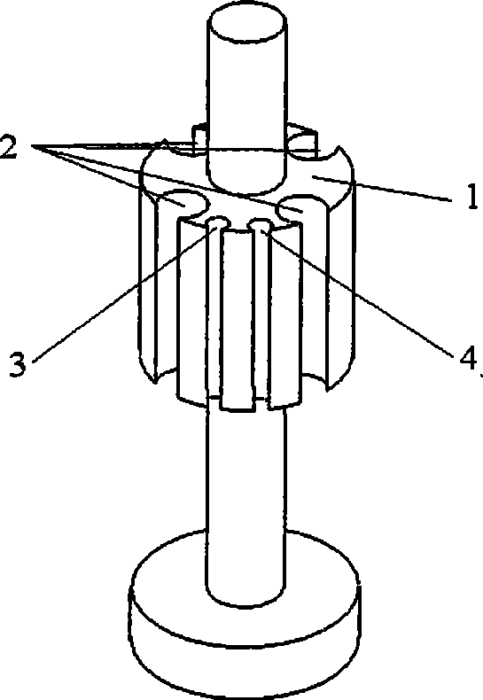
[0013] like figure 1 As shown, the device for detecting the rotational position of a superconducting spherical rotor in the present invention includes a stator skeleton 1 , a drive coil 2 , a magnetic field coil 3 and a detection coil 4 . The driving coil 2 , the magnetic field coil 3 and the detection coil 4 are arranged on the stator frame 1 . Four drive coils 2 are connected in series to form a group, and each drive coil is arranged at a distance of 90° on the stator skeleton 1 . The magnetic field coil 3 and the detection coil 4 are adjacently arranged between the two drive coils, and the magnetic field coil 3 and the detection coil 4 are adjacently arranged at 30°.

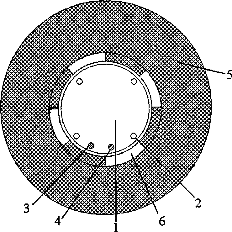
[0014] like figure 2 As shown, the hollow rotor 5 is sleeved on the stator skeleton 1, and there is a gap of 0.5mm-1mm with the stator skeleton 1. There are four windows ...


PUM


Abstract

The invention relates to a device for detecting the rotating position of a superconductive spherical rotor, which comprises a hollow rotor (5), a stator framework (1), a drive coil (2), a field coil (3) and a detection coil (4), wherein the drive coil (2), the field coil (3) and the detection coil (4) are all arranged in the middle of the stator framework (1). The rotation position of the superconductive spherical rotor is detected through the position change of a magnetic field generated by the field coil (3) in a rotor rotating inner hole window (6) and the change of induced voltage obtained by the detection coil (4). The device for driving a low-temperature superconduction spherical rotor to rotate is simple and convenient, has higher detecting and controlling precision, consumes no energy and can further increase the rotating and the driving precision and efficiency of the superconductive spherical rotor.

Description

technical field [0001] The invention relates to a rotor rotation position detection device, in particular to a device for detecting the rotation position of a superconducting spherical rotor. Background technique [0002] With the continuous development of superconducting materials and low-temperature technology, superconducting maglev technology has become more and more widely used in various fields, such as superconducting maglev trains, superconducting maglev bearings, superconducting flywheel energy storage, gravity accelerometers, etc. . The unique physical properties of superconductors have incomparable application advantages compared with other materials, especially the superconducting magnetic levitation technology has attracted more and more attention. Due to the complete diamagnetism of superconductors, that is, the Meissner effect, stable superconducting magnetic levitation can be obtained, and at the same time, this non-contact levitation can run stably without ...

Claims


Application Information

Patent Timeline
Patent Type & Authority Applications(China)
IPC IPC(8): G01B7/00G01D5/14
Inventor 胡新宁王秋良诸宁韩立
Owner INST OF ELECTRICAL ENG CHINESE ACAD OF SCI
Why Eureka
Try Eureka